12530/12540 OWNER'S MANUAL
P/N 447203 Issue I V-13
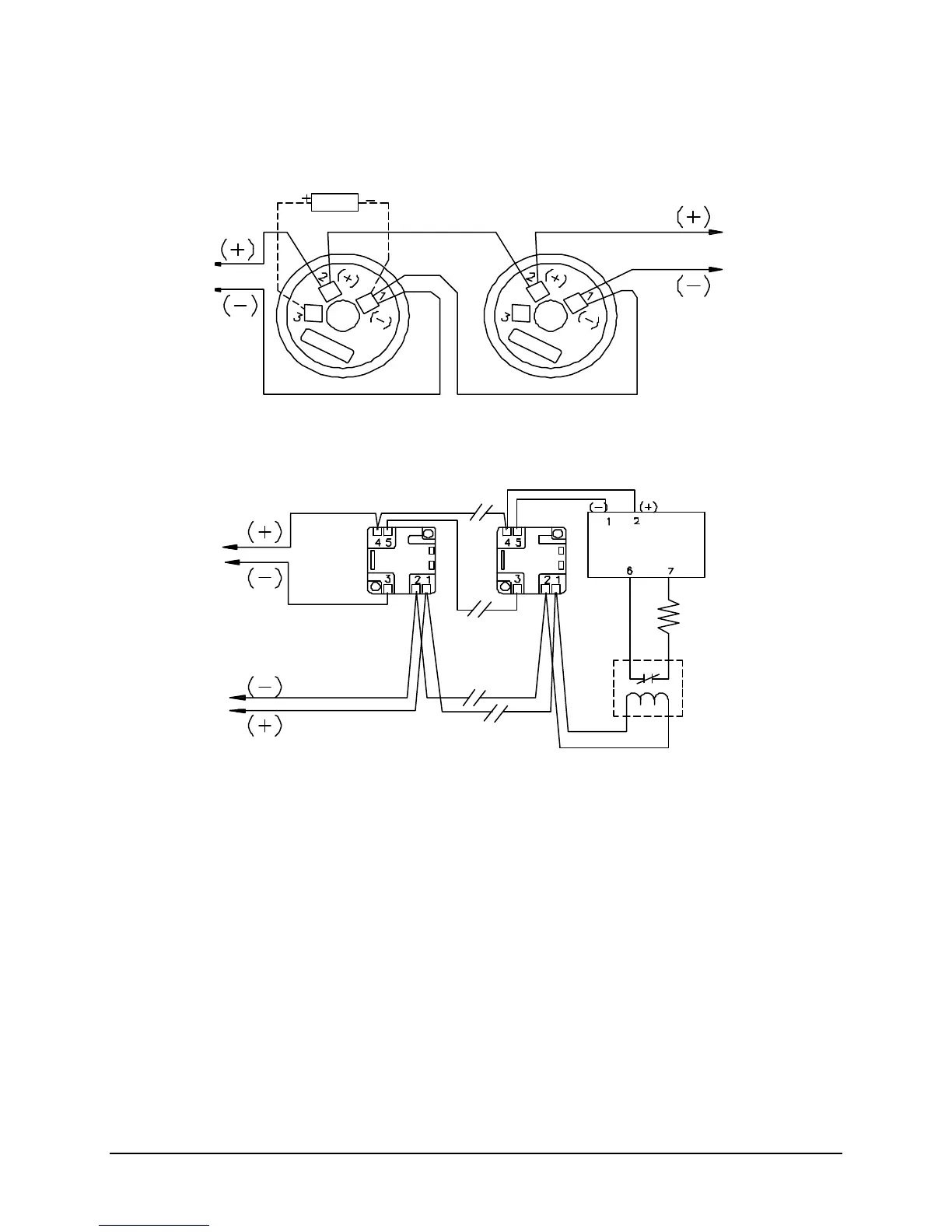
Typical Base Wiring Diagram (9155, 9181 & 9189)
Notes:
1. This wiring diagram shows only general information about this device. For specific wiring and
installation information, read the instructions provided with the device.
2. Wire Size: In alarm, no more than 3.0V drop from power supply to end of power supply loop.
3. For power supply supervision use an EOL relay with a 9157 or 9158 monitor module as shown.
(Relay contact shown with power applied)
4. From the control unit auxiliary power output or an external 24VDC regulated power supply that must
be power limited and listed for Fire Protective Signaling Use.
Power
Supply
(See Note 4)
Optional Faraday 9180 Remote Alarm
LED (System Sensor RA400Z)
Addressable
Device
Typical Horn Base Wiring Diagram (9156)
M500MB
(System Sensor A77-716B)
Device Circuit
Faraday 9155, 9181 or 9189 BASE:
(System Sensor B501B, B501 or B210LP)
(System Sensor B501BH)
Supplied with unit
Faraday 9157/9158 Monitor Module
(System Sensor M500MB/M501M)
(9157 module shown)
Device Circuit