12530/12540 OWNER'S MANUAL
P/N 447203 Issue I V-15
9161 Duct Housing for Addressable/Analog Sensors
The 9161 (System Sensor DH500AC/DC) is designed for use with an addressable/analog Ion or Photo
sensor. The 9161 is designed for 120VAC, 240VAC, 24VAC, or 24VDC to operate auxiliary functions.
Two "Form C" relay contacts are available. The LEDs on the sensor illuminate to indicate an alarm.
Remote alarm indication is made possible by utilizing the 9180 remote alarm LED unit.
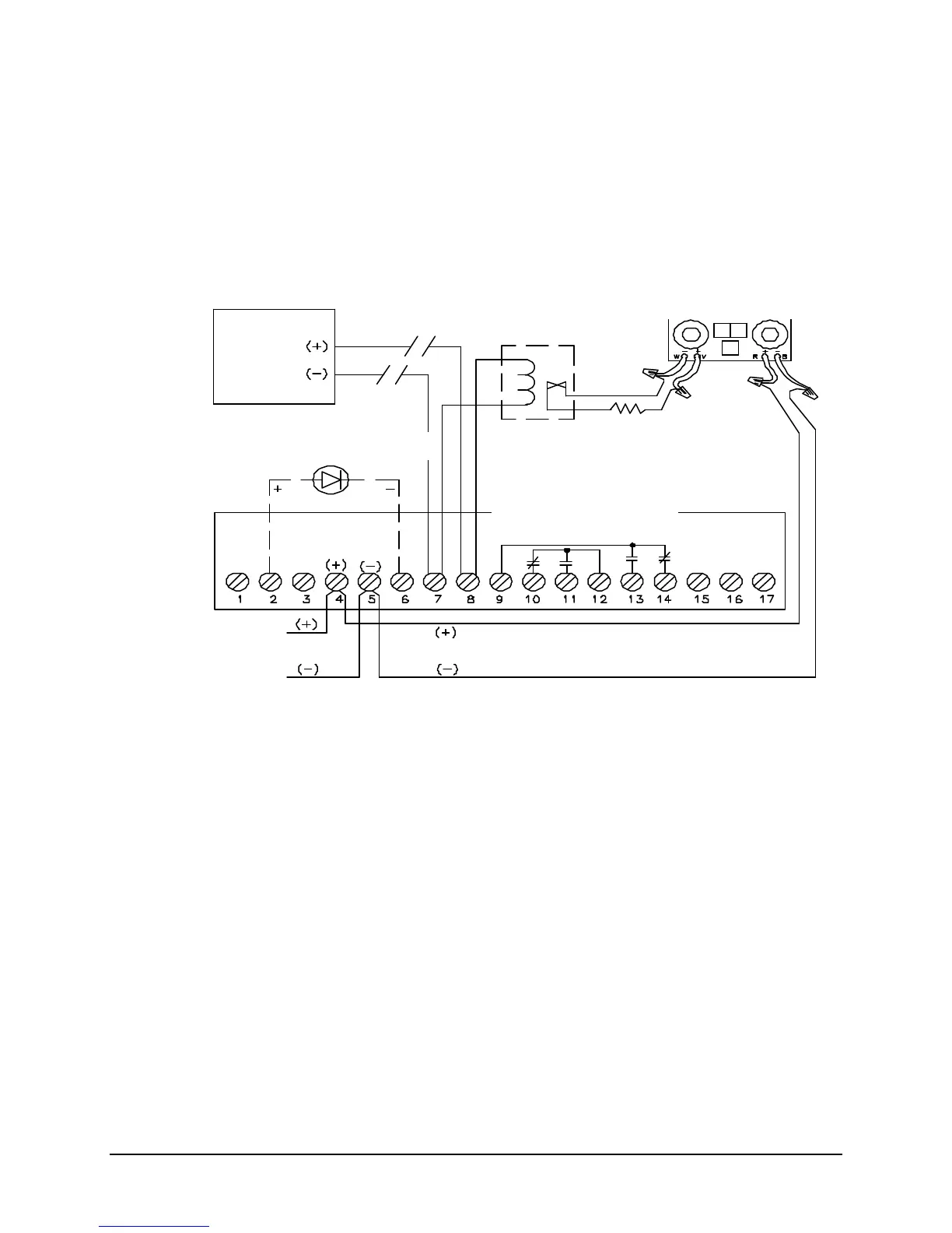
TYPICAL WIRING DIAGRAM FOR A 9161 DUCT HOUSING
FOR ADDRESSABLE ANALOG SENSOR
Notes:
1. This wiring diagram shows only general information about this device. For specific wiring and
installation information, read the instructions provided with the device.
2. Wire Size: In alarm, no more than 3.0V drop from power supply to end of power supply loop.
3. For power supply supervision use an EOL relay with a 9157 or 9158 monitor module as shown.
(Relay contact shown with power applied)
4. From the control unit auxiliary power output or an external 24VDC regulated power supply that
must be power limited and listed for Fire Protective Signaling Use.
5 9180 Remote LED and Auxiliary Control contacts will not function without separate power.
6 Relay contacts are rated at 10 Amps maximum at 30VDC, 10 Amps maximum at 277VAC, 1/2
HP at 240VAC and 360VA at 240VAC.
Power
Supply
(See Note 4)
(System Sensor A77-716B)
Faraday 9161 Duct Housing:
(System Sensor DH500AC/DC)
Supplied with unit
Faraday 9157/9158 Monitor Module
(System Sensor M500MB/M501M)
(9158 module shown)
Device Circuit
Optional Faraday 9180 Remote Alarm LED
(System Sensor RA400Z)
Addressable
Device