12530/12540 OWNER'S MANUAL
P/N 447203 Issue I V-18
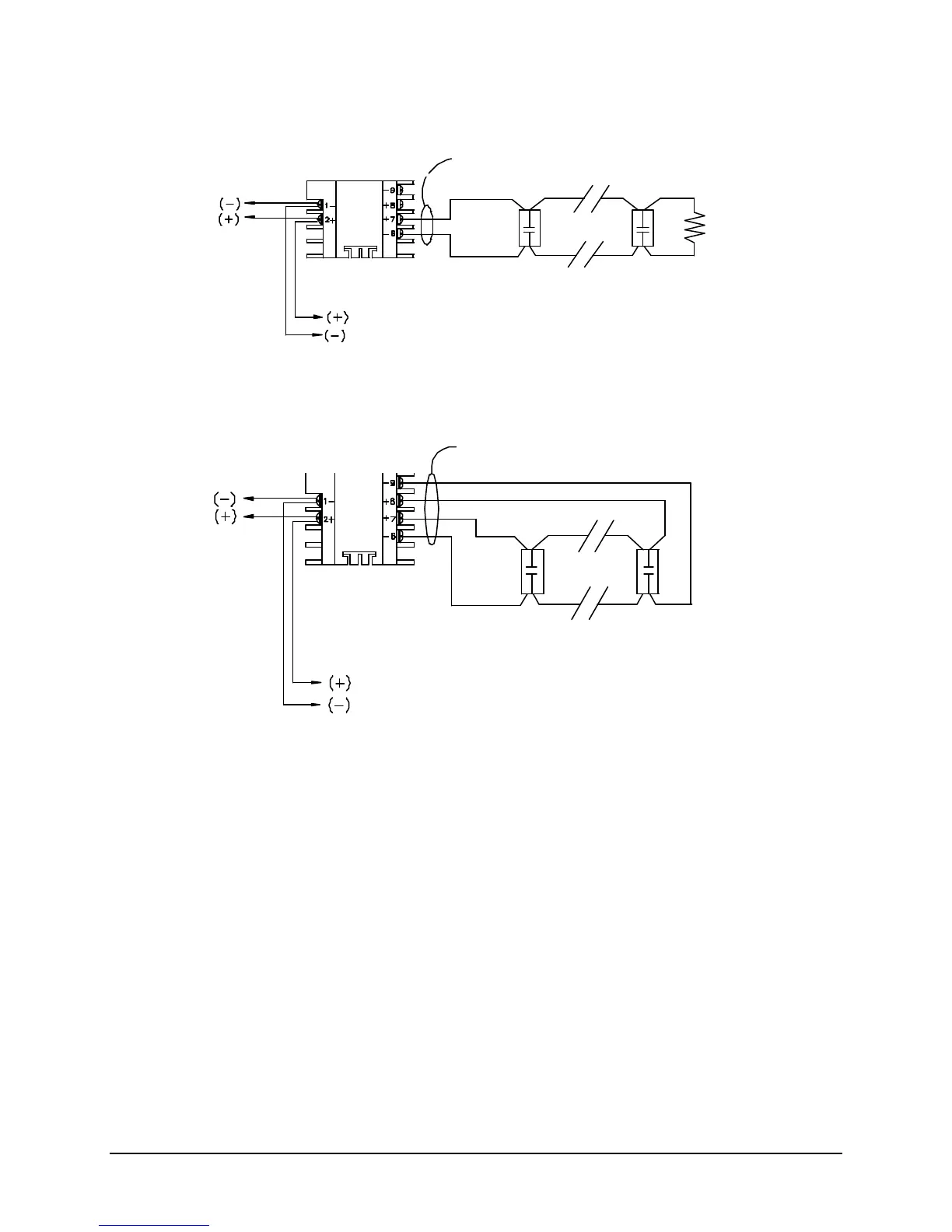
CONFIGURATION OF 9157 MONITOR MODULE
TYPICAL CONVENTIONAL STYLE “B” (“2-WIRE”) CONTACT DEVICE INITIATING CIRCUIT
CONFIGURATION OF 9157 MONITOR MODULE
TYPICAL CONVENTIONAL STYLE “D” (“4-WIRE”) CONTACT DEVICE INITIATING CIRCUIT
Notes:
1. This wiring diagram shows only general information about this device. For specific wiring and
installation information, read the instructions provided with the device.
2. Do not mix Fire & Supervisory (Tamper) Devices on the same initiating device circuit.
3. Initiating Circuit Requirements:
Maximum wire length: 2500 Ft.
Maximum wire resistance: 20 Ohms
Maximum alarm current: 230uA
4. Do not put “2-Wire” (Zone Powered) Smoke Detectors on Monitor Module Initiating loop.
5. See Article 370 of the N.E.C. for proper box depth.
Faraday 9157 Monitor Module:
(System Sensor M500MB)
Supplied with unit
Device Circuit
Addressable
Device
Power limited
Faraday 9157 Monitor Module:
(System Sensor M500MB)
Device Circuit
Addressable
Device
Power limited
See NFPA 72 for maximum quantity
of devices per initiating device circuit.
See NFPA 72 for maximum quantity
of devices per initiating device circuit.