12530/12540 OWNER'S MANUAL
P/N 447203 Issue I V-22
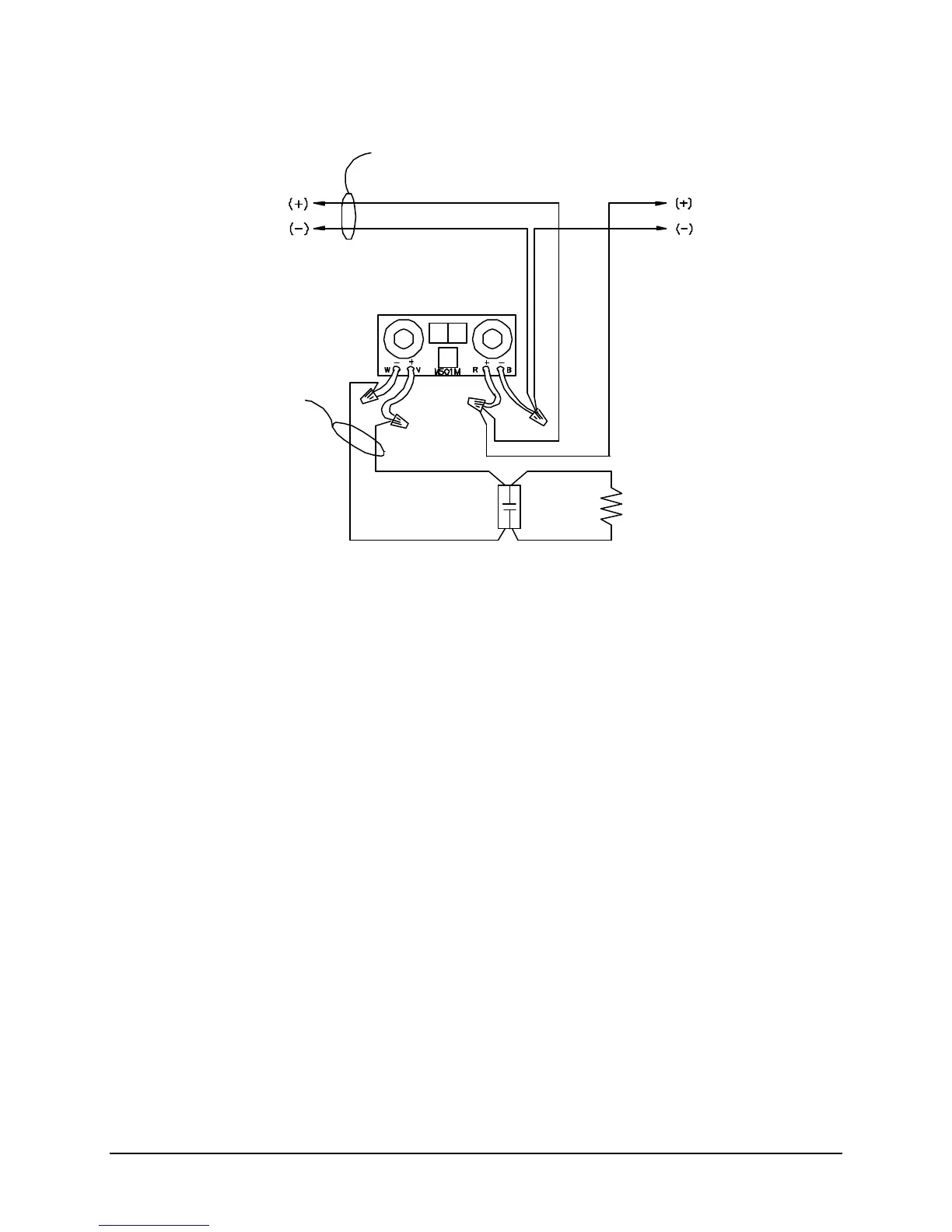
CONFIGURATION OF 9158 MONITOR MODULE
TYPICAL CONVENTIONAL STYLE “B” (“2-WIRE”) INITIATING CIRCUIT
Notes:
1. This wiring diagram shows only general information about this device. For specific wiring and
installation information, read the instructions provided with the device.
2. Do not mix Fire & Supervisory (Tamper) Devices on the same initiating device circuit.
3. Initiating Circuit Requirements:
Maximum wire length: 2500 Ft.
Maximum wire resistance: 20 Ohms
Maximum alarm current: 230uA
4. Do not put “2-Wire” (Zone Powered) Smoke Detectors on Monitor Module Initiating loop.
5. See Article 370 of the N.E.C. for proper box depth.
Faraday 9157 Monitor Module:
(System Sensor M501M)
Device Circuit
Addressable
Device
Power limited
See NFPA 72 for maximum quantity
of devices per initiating device circuit.
Supplied with unit
Power limited