12530/12540 OWNER'S MANUAL
P/N 447203 Issue I V-24
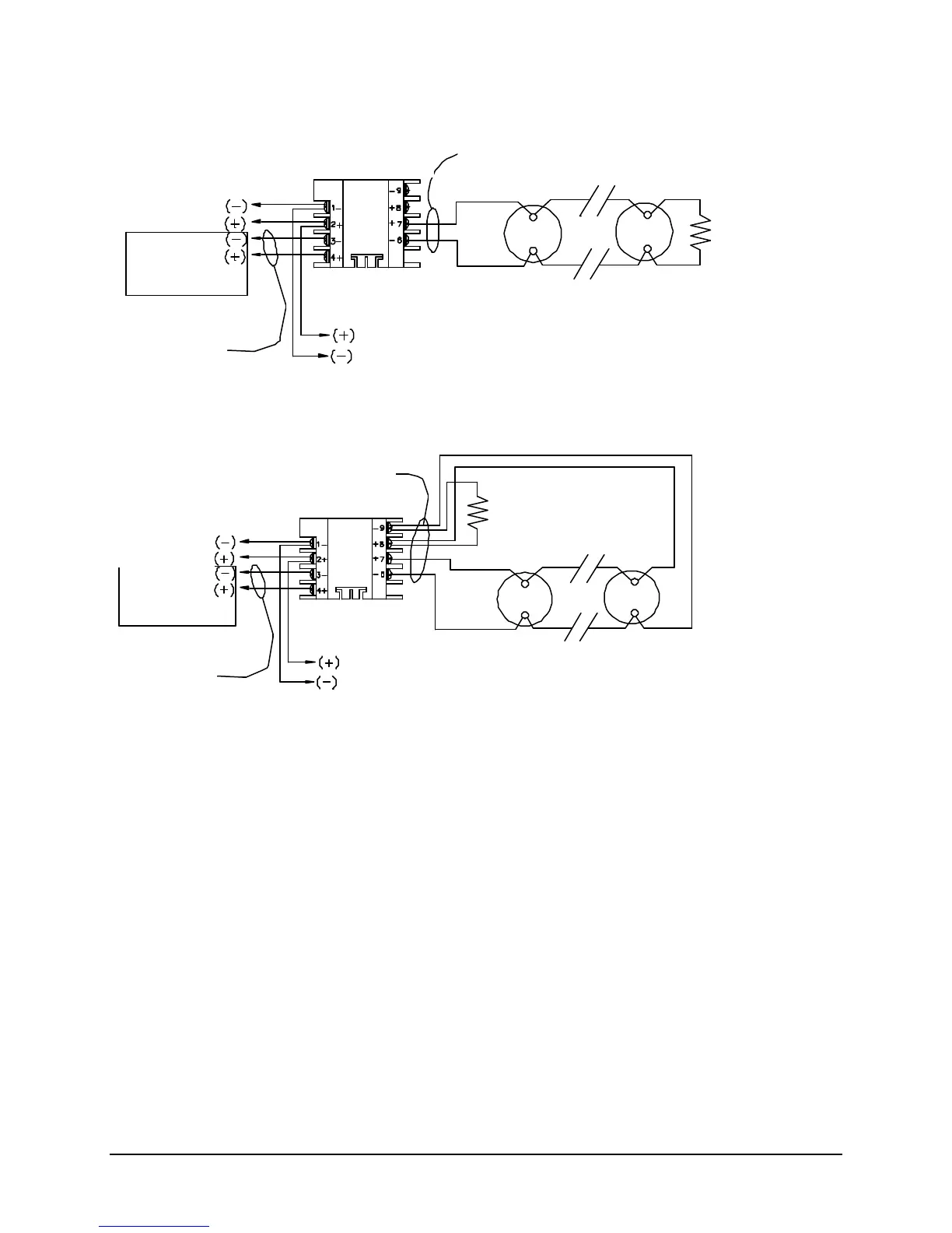
CONFIGURATION OF 9191 MONITOR MODULE
TYPICAL CONVENTIONAL STYLE “B” (“2-WIRE”) CONTACT DEVICE INITIATING CIRCUIT
CONFIGURATION OF 9191 MONITOR MODULE
TYPICAL CONVENTIONAL STYLE “D” (“4-WIRE”) CONTACT DEVICE INITIATING CIRCUIT
Notes:
1. This wiring diagram shows only general information about this device. For specific wiring and
installation information, read the instructions provided with the device.
2. Do not mix Fire & Supervisory (Tamper) Devices on the same initiating device circuit.
3. Initiating Circuit Requirements:
Maximum wire resistance: 25 ohms
Maximum alarm current: 92mA
4. Use only UL compatible “2-Wire” (Zone Powered) Smoke Detectors listed in the installation
instructions.
5. See Article 370 of the N.E.C. for proper box depth.
6. From the control unit resettable auxiliary power supply output or an external 24VDC regulated
power supply that must be power limited and listed for Fire Protective Signaling Use.
Faraday 9191 Monitor Module:
(System Sensor M502M)
Device Circuit
Addressable
Device
Power limited
Supplied with unit
Power limited
Power
Supply
(See Note 6)
Faraday 9191 Monitor Module:
(System Sensor M502M)
Device Circuit
Addressable
Device
Power limited
Power limited
Power
Supply
(See Note 6)
Supplied with unit