DAZZLER
TM
system manual Part I : installation & operation 8.8
• protectp = ”protection period”, triggers are disabled during this time, so as to protect
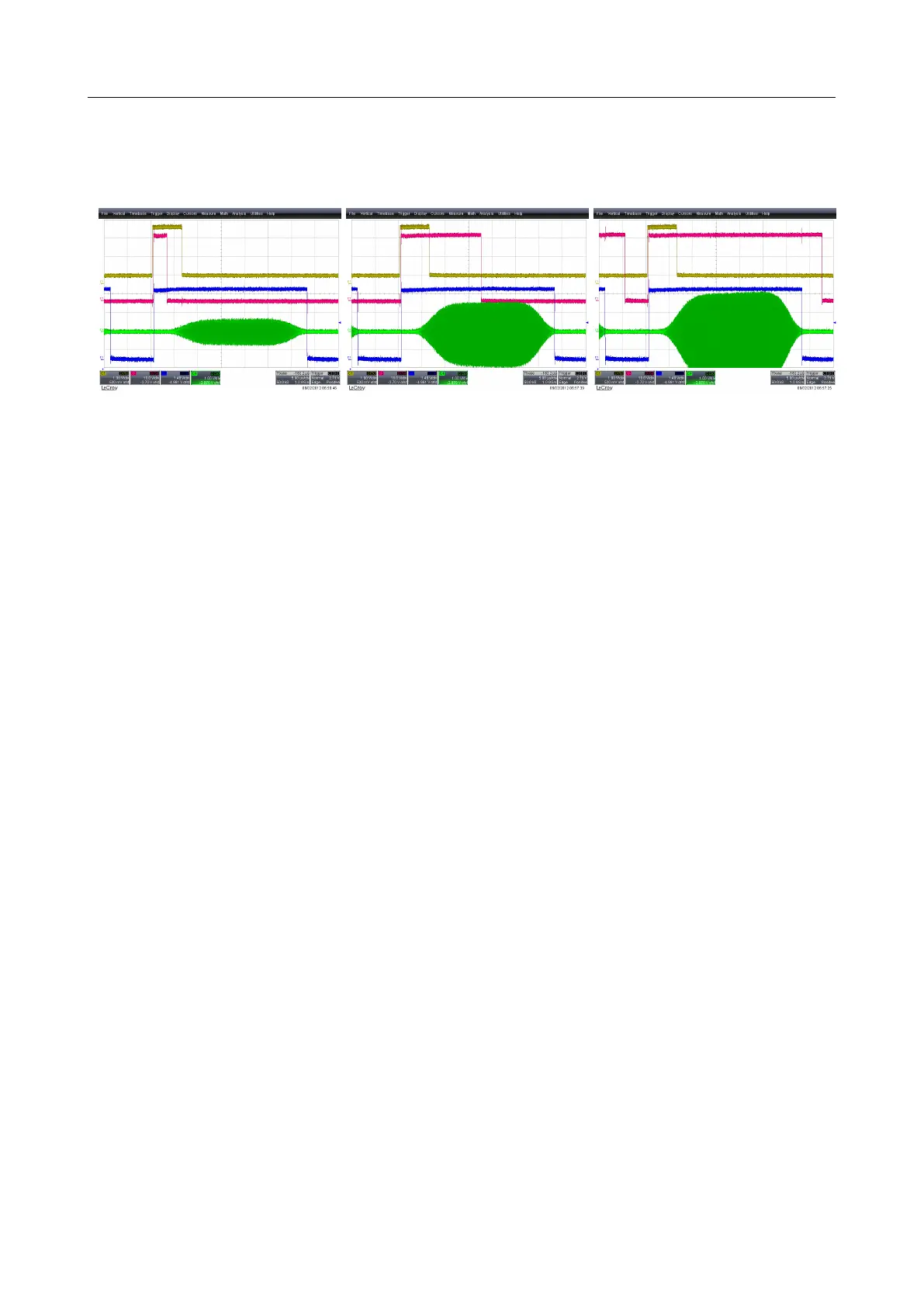
the crystal from thermal damage. The following pictures show increasing power, the red
trace is protectp, the green trace is the RF signal and gate is on the blue trace.
Figure 8.8: prevent thermal damage by disabling triggers during protectp
• GND - VCC or logic values LO - HI: these levels are used to verify the operation or cabling. In
Mazzler mode, S2 is used to control a shutter. Beware that these levels are NOT guaranteed
to be steady. During the operation of the Dazzler program, they may be pulsing. They are
steady if the Dazzler
TM
program is only polling.
• fsmpcnt(4) & fsmpcnt(5) are the sampling frequency divided by 32 and 64: used to verify the
operation or cabling. When in low jitter operation, can be used to connect a frequency meter
and verify that the reference clock is correct.
• Qclock is the internal quartz clock divided by 4 (20 MHz). Used to verify operation.
• gatebasic is the gating signal when operating in the ”high rep rate” oscillator mode (gating
option), see subsection 4.3.5.
• hwabusy and hwstrobe are handshake signals for the ’hardware addressing’ option.
• seqparity is related to the sequence option in burst mode. The signal is reset when waiting
for the burst trigger. It increments on each sequence line.
V3.00 - 8
th
April 2019 (ContentsTable) (FiguresTable) 90/94