2.5 Grounding Requirements Section 2: Installation
CV-6SLX User Manual 0101-8242-0, Rev. C
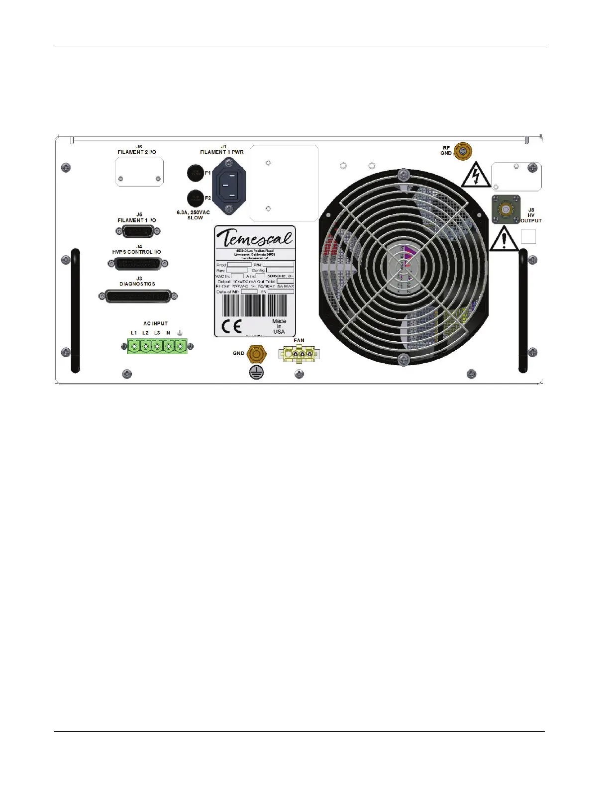
2 Secure one end of this strap to the grounding stud labeled RF GND
on the power module’s rear panel (see Figure 2-4).
Figure 2-4 Rear Panel of CV-6SLX HVPS
3 Secure a length of #10 AWG wire to the grounding lug labeled GND
on the power module rear panel.
4 Secure the loose end of the 1/2” copper strip and the loose end of
the #10 AWG ground wire to a clear, bare patch of metal on the
operator station’s frame. The same fastener that secures the above
copper strip to the frame should also secure one end of a length of
3” copper strap that connects to the vacuum cubicle’s central
grounding point, as shown in Figure 2-3.
2.5.4 Filament Power Supply Grounding
Make connections to the grounding lugs on the FPS front panel as shown in in the CV-6SLX
Quick Start Guide (PN 0101-8241-1), following the procedure described below.
Step Action
1 Cut a length of 1/2”-wide copper strap (user-supplied) that will
easily extend from the filament power supply to the vacuum
cubicle’s central grounding point.
2 Secure one end of this strap to the grounding stud labeled RF GND
on the FPS front panel (see Figure 2-5).
 Loading...