5.3 Ishikawa Diagrams Section 5: Troubleshooting
CV-6SLX User Manual 5-8 0101-8242-0, Rev. C
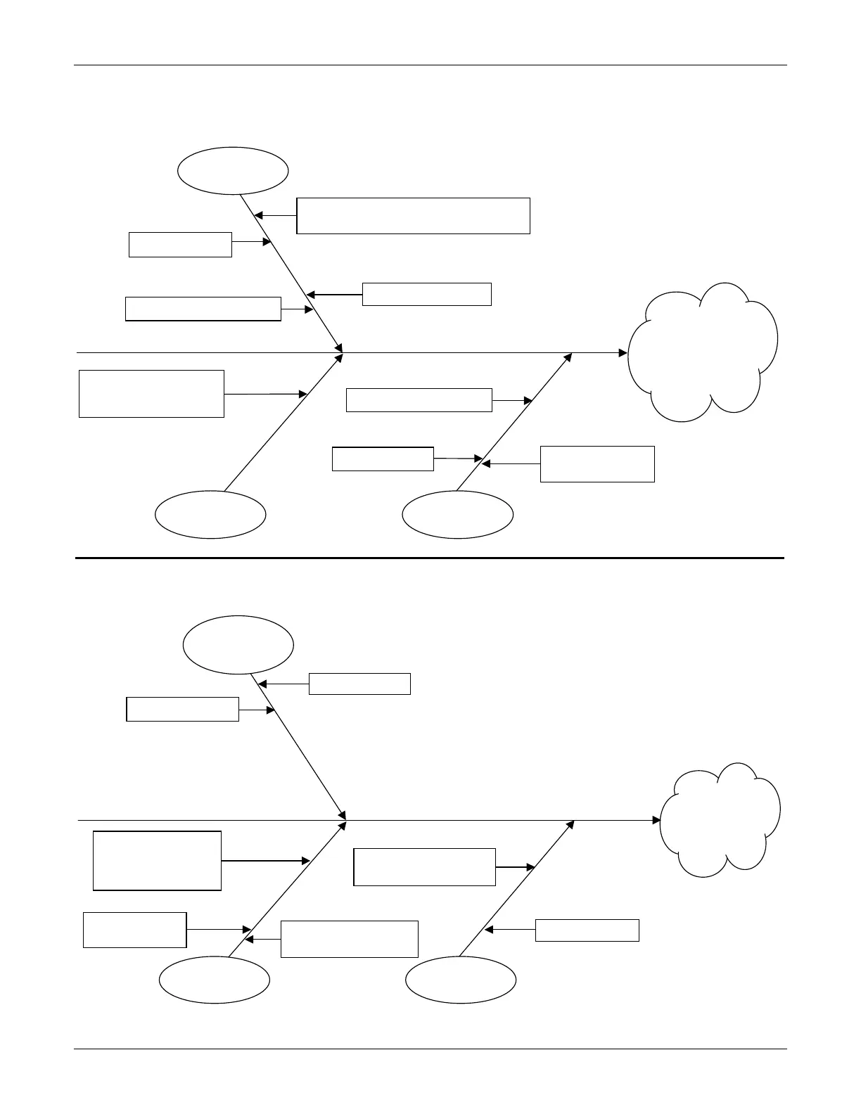
Ishikawa Diagram #3: No Beam After HV and Gun Are Switched ON
Ishikawa Diagram #4: HV Output Unstable
Interface/
External control
Filament bias setpoint
not present
Nominal value setpoint input
from external input or gun
controller not correct
HV not present at emitter
Emitter incorrectly assembled
HV and gun switched ON
but no beam is emitted
(see Table 6-8)
Loose or faulty connections
Loose or faulty connections in emitter assembly,
feedthrough, or interconnection path
HV output unstable
(see Table 6-9)
Problem with HV path, loose
connection, shorting
Incorrect feedback
communication between
A5 HV Output PCB and
A3 HV Regulator PCB
Defective A5
HV Output PCB
HV output cable defective/
not connected
 Loading...