2.6 Cable Installation Section 2: Installation
CV-6SLX User Manual 0101-8242-0, Rev. C
2.6.1 Connecting the Input Power Cables
Connecting the Power Module Input Power Cable
CAUTION
Make sure that the main power breaker on the HVPS front panel is in the OFF
position and remains in that position throughout the installation procedure.
The CV-6SLX is available for the following input voltages:
• 208-V Model CV-6SLX (PN 6024-7110-0), 50/60 Hz, 3-Phase delta, 4-wire
Connect using AWG #10 stranded UL1015 wire
• 400-V Model CV-6SLX (PN 6024-7120-0), 50/60 Hz, 3-Phase wye, 5-Wire with neutral
Connect using AWG #12 stranded UL1015 wire
The input power cable is user supplied and must conform to the specifications listed above.
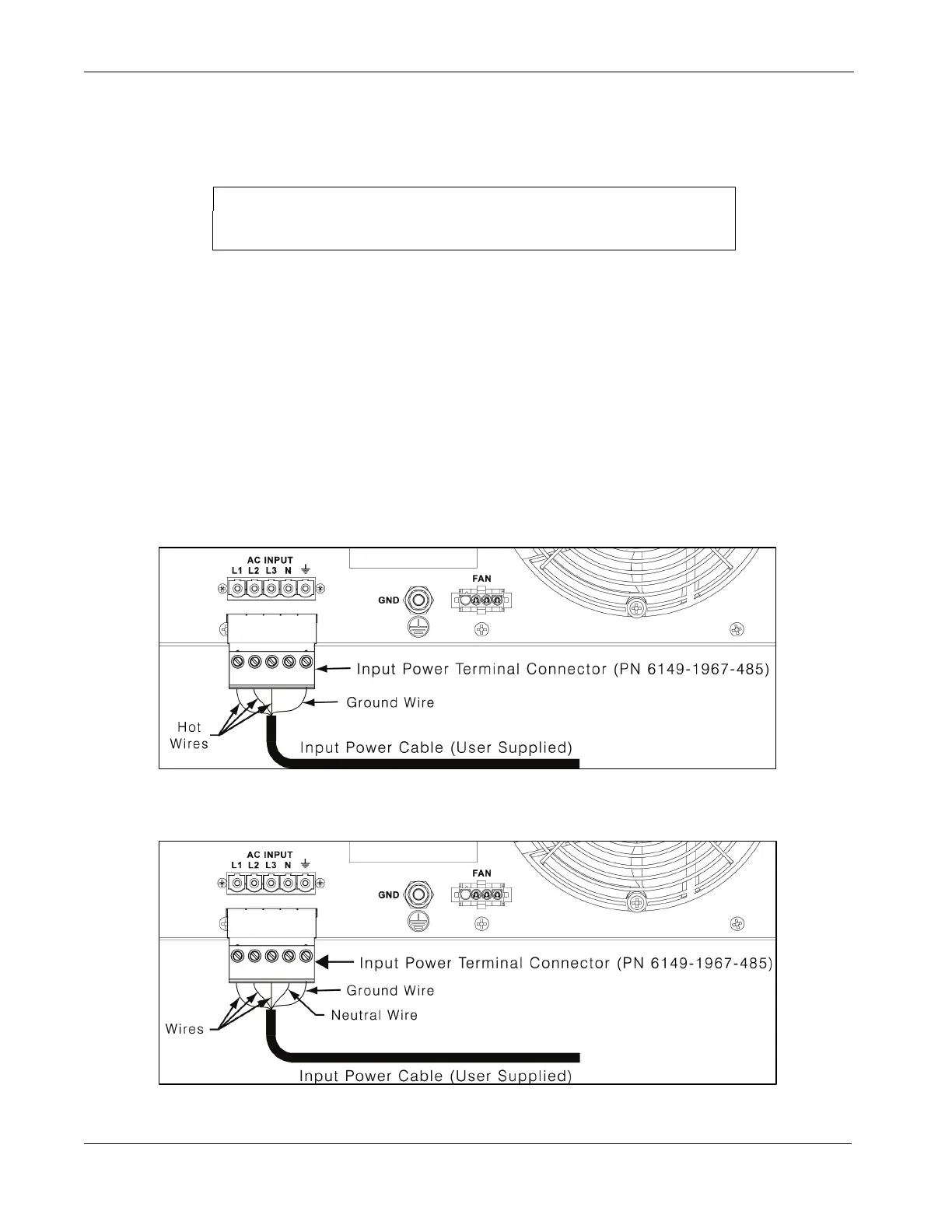
On 208-volt units, connect the input power cable as shown in Figure 2-6. On 400-volt units,
connect the input power cable as shown in Figure 2-7. Then plug the input power terminal
connector into the terminal strip on the HVPS rear panel and secure it with the screws
provided for that purpose.
Figure 2-6 Input Power Connections to 208-Volt HVPS Units
Figure 2-7 Input Power Connections to 400-Volt HVPS Units
 Loading...