Section 3: Power Supply Operation 3.6 Control of Power Supply by a PLC-Based System Controller
0101-8242-0, Rev. C 3-9 CV-6SLX User Manual
NOTE
The main power breaker on the power module front panel controls power to the filament power supply
(FPS) module.
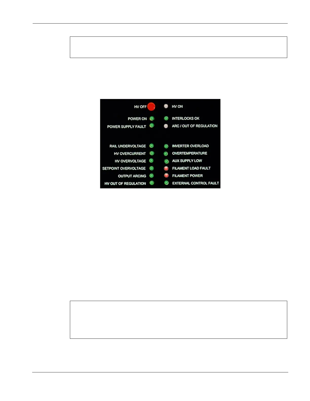
Figure 3-10 shows the HVPS front panel LEDs when the unit is powered up and in its nominal
state (i.e., no faults have occurred) but before the HV and the FPS have been switched on.
Figure 3-10 HVPS Front Panel LEDs: HVPS Powered Up in Nominal State, with HV and FPS Off
For additional information about HVPS front panel LEDs, see section 5.2.
3.6.2 High Voltage Control
Switching On the High Voltage Under Normal Operating Conditions
In order for the HV to be switched on, the LEDs on the HVPS front panel must be in the state
shown in Figure 3-10. Then the external controller or control system must assert HV ON IN
signal for two seconds at Pin 8 of HVPS rear panel connector J4 (see Table 2-1).
Switching On the High Voltage Following a Latching Fault Condition
Switching off the HV by pressing the HV OFF button on the power module front panel triggers a
latching Power Supply Fault. In that event, or when any other latching fault has occurred, the
following signals must supplied, in the order given below, to switch the HV back on.
NOTE
If a Power Supply fault has occurred because of a latching fault condition—and not because the user
has pressed the power module’s HV OFF button—the underlying fault that triggered the latching fault
must be corrected before the HV can be reset. For detailed information about fault indicator LEDs, see
section 5.2. For diagrams illustrating the troubleshooting logic that applies to various fault conditions,
see section 5.3. For troubleshooting procedures, see section 5.4.
1. The RESET signal must be supplied via Pins 10 and 11 of HVPS rear panel connector J4 (see
Table 2-1). If the RESET attempt is successful, all status and interlock LEDs on the power
module should be green, except for HV ON and ARC/OUT OF REGULATION..
 Loading...