4.3 FPS Theory of Operation Section 4: Theory of Operation
CV-6SLX User Manual 0101-8242-0, Rev. C
4.3.3 Filament Supply PCB
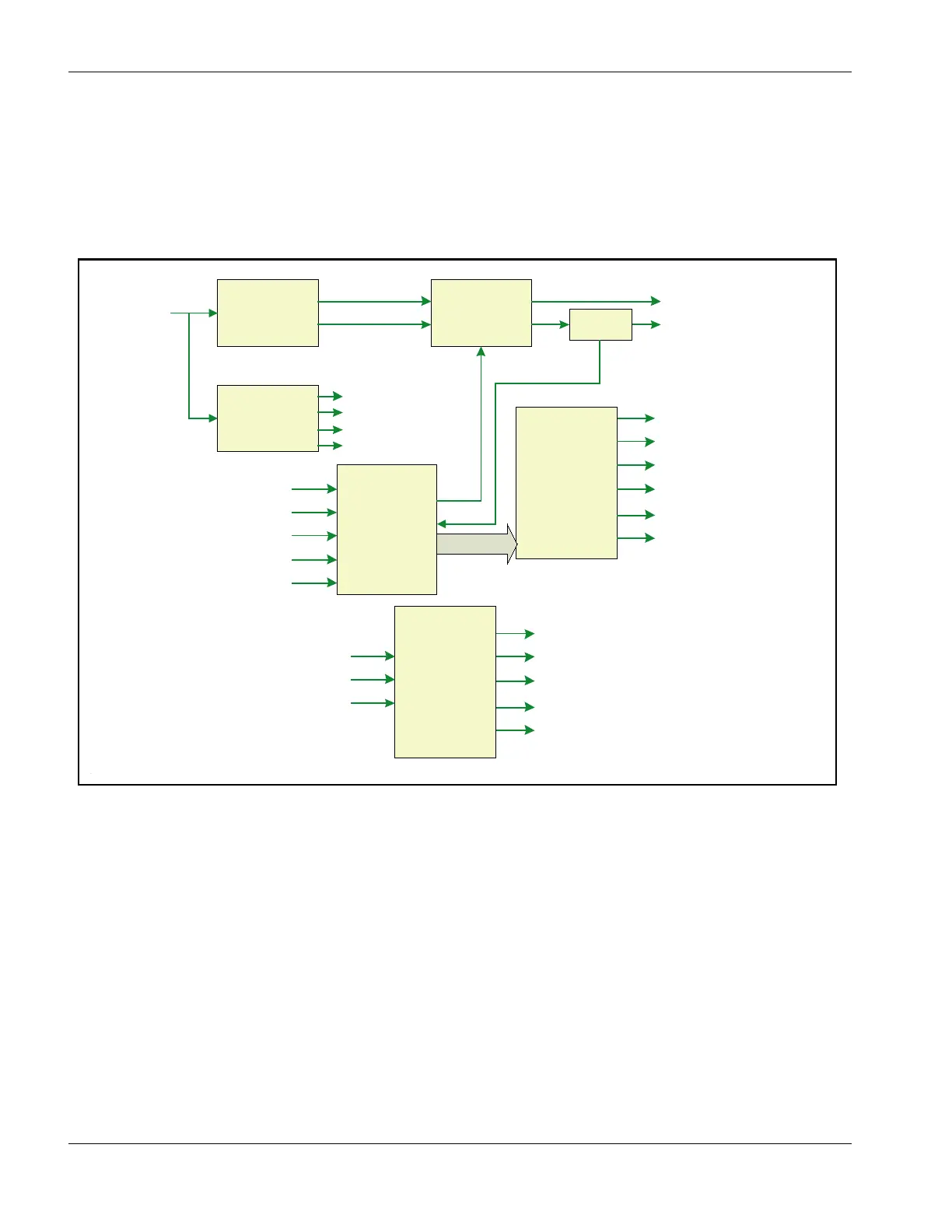
Figure 4-8 is a top-level block diagram for the Filament Supply PCB, whose circuits are described
in detail below.
Figure 4-8 Filament Supply PCB Overview Block Diagram
Filament DC Voltage Supply for Switch Mode Converter
A single-phase bridge rectifier circuit provides the raw dc power for the high-frequency switches.
The DC voltage is filtered and a + (positive) rail voltage and a - (negative) rail voltage is
established. The single-phase 220-V power for the filament and positions circuits enters on J104
Pin 1 and 4. The circuit is protected by fuses F-1 and F-2. The ac power is rectified by DB-10
and filtered by inductors L-10 and L-11 in combination with rail capacitors C-11 and C-12.
Low-Voltage DC Supplies
Low DC voltages of +24 V, +12 V, +5 V and –12V are supplied by T-102 via bridge rectifiers DB-
14 and DB-14. +12 V and +5V are down-regulated from +24 V by VR-101 and VR-103. -12 V is
down-regulated from –24 V by VR-102. These supplies provide power for the logic and control
circuits on the board.
Filament
DC Voltage
Supply
Filament
Current
Control
Circuits
Low
Voltage
DC Supplies
Filament
Switch Mode
Supply
FILAMENT BIAS SET IN
EMISSION REQUESTIN
+ 24 V
208 -220
VAC
GUN GOONIN
AUTO-BIAS ACTIVATE IN
ABIAS _RESET _IN
- 12 V
+ 5 V
+ 12 V
Current
Sense
Gun
Control
Monitor
Outputs
FILAMENT CURRENT MONITOR
EMISSION MONITOR OUT
GUN IS READYOUT
GUN IS ON OUT
AUTO-BIAS INDICATOR HI
AUTO-BIAS INDICATOR LO
HVPS
Status
EM MON
FIL IMON
HV INTERLOCK OUT
FIL PWR OK
FIL OK /OPEN
H VIS ON IN
HV INTERLOCK IN
HV IN REGULATION IN
PRIMARYFILAMENT VOLTAGE
 Loading...