5.3 Ishikawa Diagrams Section 5: Troubleshooting
CV-6SLX User Manual 5-14 0101-8242-0, Rev. C
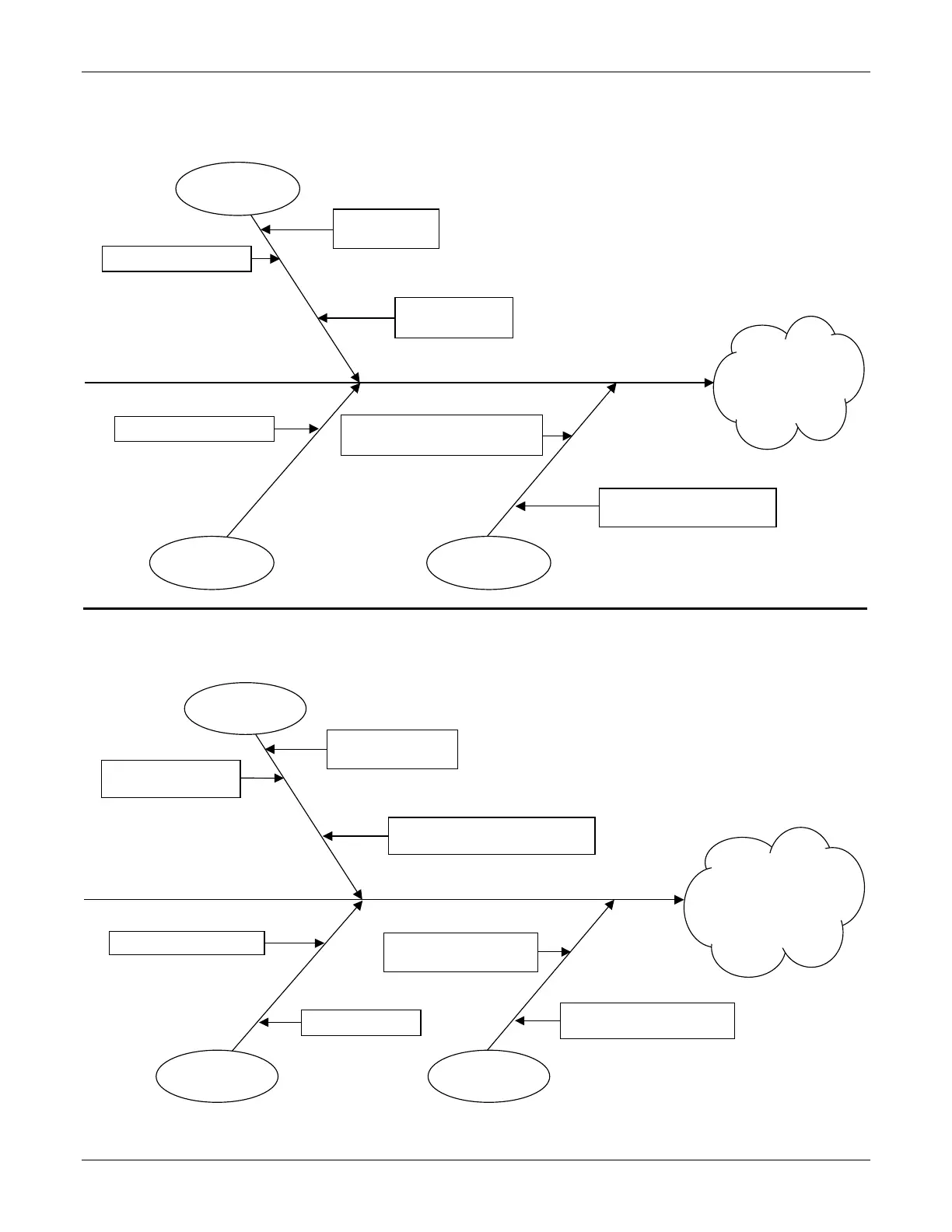
Ishikawa Diagram #15: Filament Load Fault
Ishikawa Diagram #16: Simultaneous Filament Load Fault + Filament Power Fault
Cable not connected between
J102 on FPS and J5 on HVPS
A5 Interface PCB defective
Filament Load Fault
LED lights red
(see Table 6-22)
HV feedthrough
damaged or coated
Dirty/damaged
emitter assembly
Incorrect filament status signal from
FPS. +24 VDC from J102 Pin 6
Filament Load Fault and
Filament Power LEDs
both light red (see
Tables 6-22 and 6-23)
No connection between
HVPS J5 and FPS J102
Fuses F1/F2 on AC input J104
switch blown
A5 Interface PCB defective
FPS power switch in OFF
position
HVPS J2 to AC power cable defective
or incorrrectly connected
HVPS to FPS interface
cable defective
 Loading...