4.3 FPS Theory of Operation Section 4: Theory of Operation
CV-6SLX User Manual 0101-8242-0, Rev. C
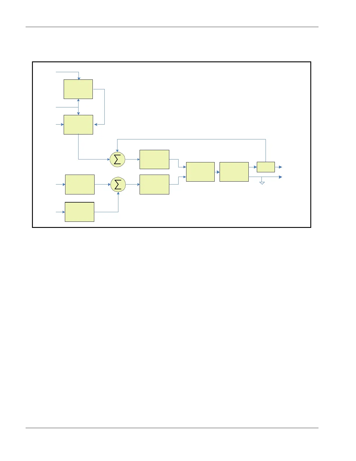
Figure 4-9 Block Diagram of Filament Supply PCB Control and Power Circuits
Emission Current Control Loop
When emission current (ECR) is called for the emission current loop control comes into play and
the filament current control loop is ignored. ECR is first buffered by A105 and then fed to the
10-sec ramp circuit to gradually increase the emission current to the desired level. The output of
the ramp circuit U103-2 is fed to inverting buffer U205A to the summing junction of the emission
current loop compensation circuit of U106A via R54. The emission current feedback signal,
Emission Monitor (EM) comes from the HV current transducer in the Filament Output Section of
the FPS and is scaled by a rotary switch selection of gain values for buffer A101. The output of
A101 is also fed to the summing junction of the emission current loop compensation circuit of
U106A via R52. As above, the output of U106A feeds the PWM U101-2 via buffer U106B to drive
the switch mode power inverter.
Emission Current Request Ramp
Figure 4-10 is a block diagram for the emission current ramp circuit, which allows the gradual
increase of emission current in 255 steps. When the Emission Request, Gun On, HV On, and HV
In Reg signals are asserted, clock U104 begins clocking 8-bit counter U11 from its cleared state.
When U11 counter reaches 255 the AND of its outputs stops the clock oscillator. The eight
outputs of the counter drive the 8-bit digital to analog converter U103. The output of the D/A is
the count times the Emission Current Request Signal divided by 256.
 Loading...