6. Electrical installation
108 Festo.P.BE-CMMS-ST-G2-HW-EN 1008NH
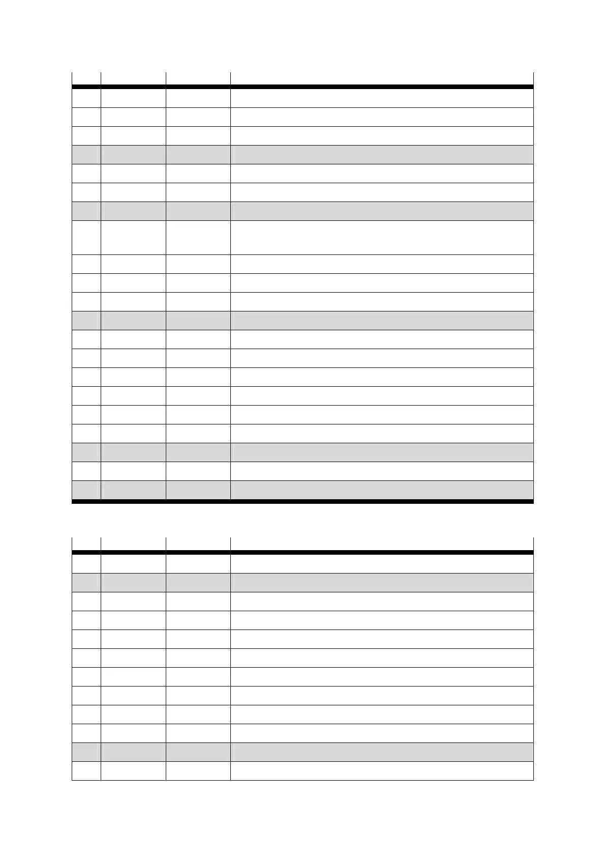
Pin Name Value Mode = 2 - Record linking
5 Unassigned
6 GND24 Reference potential for digital inputs and outputs
7 DIN1 Record selection 1 (high active)
8 DIN3 Stop record linking
9 DIN5 Controller enable (high active)
10 DIN7 Limit switch 1
11 DIN9 Mode switch record linking “1”
12 DOUT1 24 V 100 mA Output freely programmable
default motion complete (high active)
13 DOUT3 24 V 100 mA Output freely programmable - default error (low active)
14 AGND 0 V Reference potential for the analogue signals
15 DIN13 Stop input (low active)
16 DIN11 Next 2
17 AMON0 0...10 V ±4% Analogue monitor output 0
18 + 24 V 24 V 100 mA 24 V supply carried out
19 DIN0 Record selection 0 (high active)
20 DIN2 Record selection 2 (high active)
21 DIN4 End stage enable (high active)
22 DIN6 Limit switch 0
23 DIN8 Start record linking
24 DOUT0 24 V 100 mA Ready for operation output (high active)
25 DOUT2 24 V 100 mA Output freely programmable - default start ack (high active)
Table 6.4 Pin allocation: I/O interface [X1] Mode 2
Pin Name Value Mode = 3 - Synchronisation
1 AGND 0 V Screen for analogue signals
2 DIN12 Slave synchronisation “1”
3 DIN10
4 +VREF +10 V ±4% Reference output for setpoint potentiometer
5 Unassigned
6 GND24 Reference potential for digital inputs and outputs
7 DIN1
8 DIN3 24 V Direction_24 /CCW
9 DIN5 Controller enable (high active)
10 DIN7 Limit switch 1
11 DIN9 Slave synchronisation “1”
12 DOUT1 24 V 100 mA Output freely programmable - default motion complete (high active)

 Loading...


