6. Electrical installation
106 Festo.P.BE-CMMS-ST-G2-HW-EN 1008NH
6.4 Interfaces
6.4.1 I/O interface [X1]
Mode switching allows assignment of the [X1] interface more than once.
As a result, a maximum of four different I/O assignments can be selected.
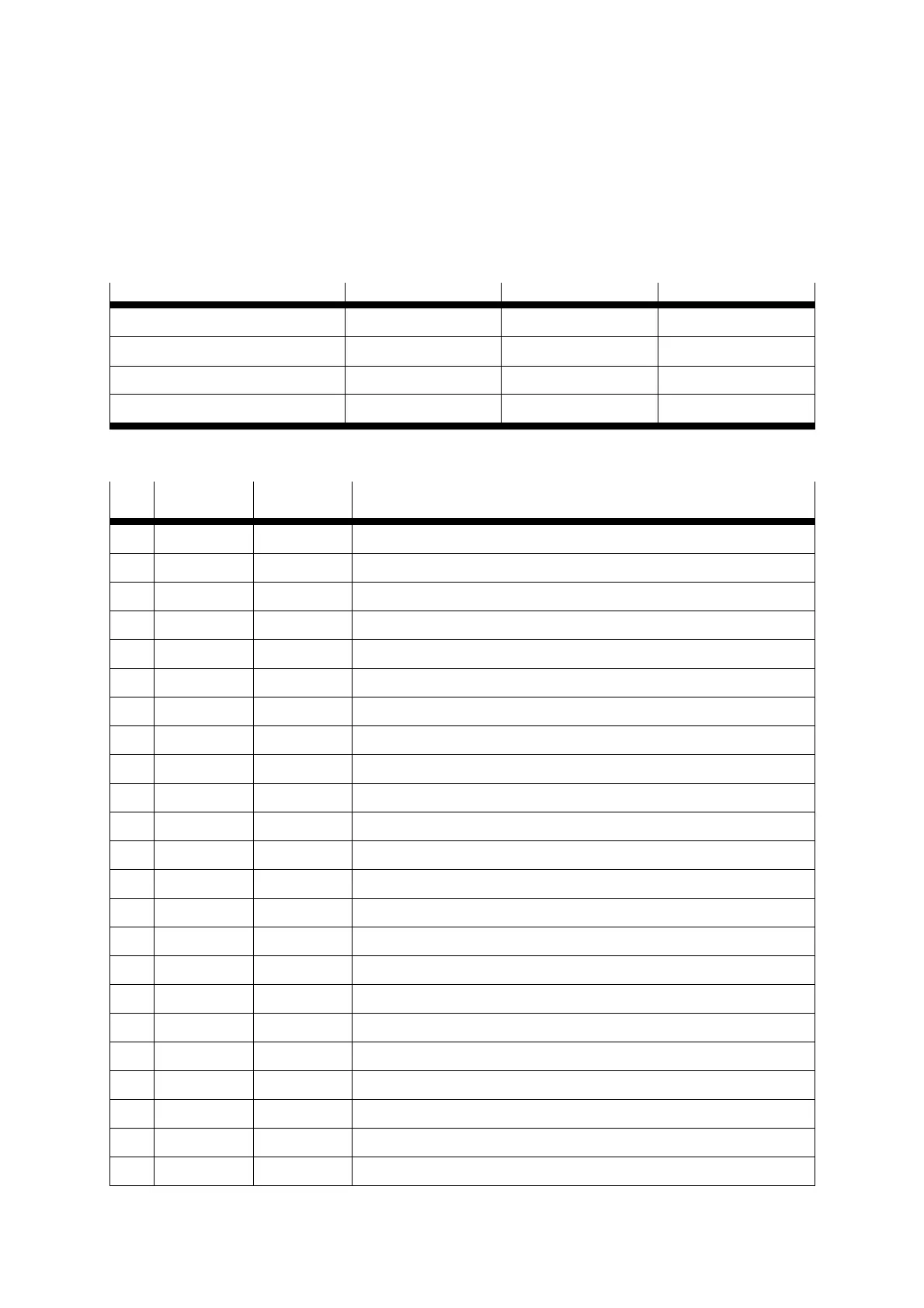
Mode DIN9 DIN12 Table
Mode 0 – Positioning 0 0
Table
6.2
Mode 1 – Jog mode 0 1
Table
6.3
Mode 2 – Record linking 1 0
Table
6.4
Mode 3 – Synchronisation 1 1
Table
6.5
Table 6.1 Mode switching
Pin Name Value Mode = 0 - Positioning
1 AGND 0 V Screen for analogue signals
2 AIN0 ±10 V Setpoint input 0, differential, maximum 30 V input voltage
3 DIN10 Record selection 4 (high active)
4 +VREF +10 V ±4% Reference output for setpoint potentiometer
5 Unassigned
6 GND24 Reference potential for digital inputs and outputs
7 DIN1 Record selection 1 (high active)
8 DIN3 Record selection 3 (high active)
9 DIN5 Controller enable (high active)
10 DIN7 Limit switch 1
11 DIN9 High-speed input
12 DOUT1 24 V 100 mA Output freely programmable – Default: Motion complete (high active)
13 DOUT3 24 V 100 mA Output freely programmable – Default: Error (low active)
14 AGND 0 V Reference potential for the analogue signals
15 DIN13 Ri = 20k Stop input (low active)
16 DIN11 Record selection 5 (high active)
17 AMON0 0...10 V ±4% Analogue monitor output 0
18 + 24 V 24 V 100 mA 24 V supply carried out
19 DIN0 Record selection 0 (high active)
20 DIN2 Record selection 2 (high active)
21 DIN4 End stage enable (high active)
22 DIN6 Limit switch 0
23 DIN8 Start for the positioning procedure

 Loading...


