6. Electrical installation
Festo.P.BE-CMMS-ST-G2-HW-EN 1008NH 103
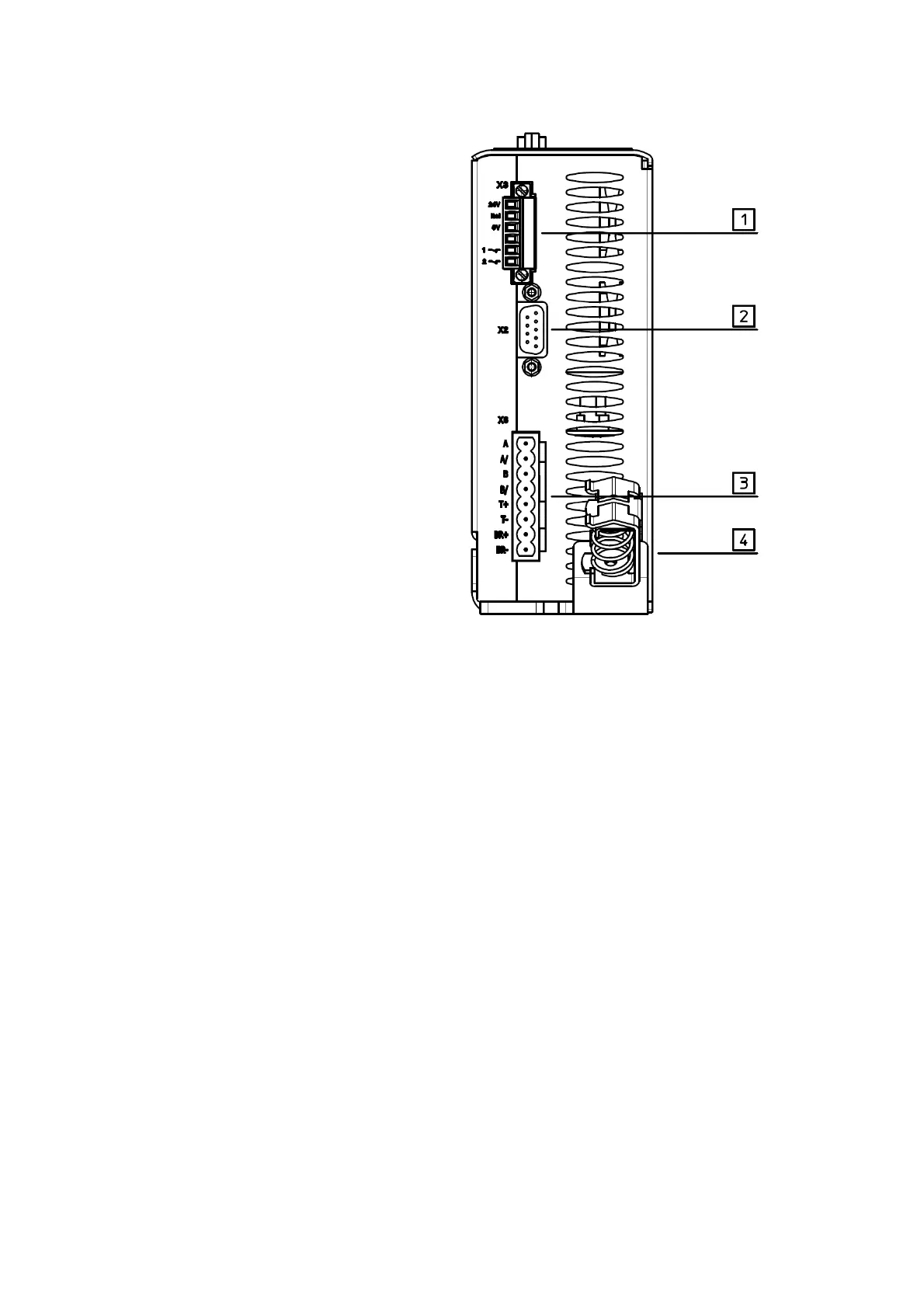
1 [X3] Safe standstill
2 [X2] Increment generator input
3 [X6] Motor connection
4 Screened connection
Fig. 6.3 CMMS-ST bottom view
6.2 Interfaces
In order to operate the CMMS-ST stepping motor controller, a 24 V power source is
initially needed to supply the electronics systems. It is connected to terminals +24 V
and 0 V.
The supply voltage for the power output stage is connected to contacts ZK+ and 0 V.
The motor is connected with the four terminals A ... B/.
The connection of the optional shaft encoder via the d-sub plug to [X2] is illustrated in the
diagram Fig.
6.4.
The CMMS-ST stepping motor controller must first be fully wired. Only then can the
operating voltages be activated for the intermediate circuit and the power supply. If the
polarity of the operating voltage connections is reversed, or if the operating voltage is
too high or the operating voltage and motor connections are incorrectly connected, the
CMMS-ST stepping motor controller will be damaged.

 Loading...


