7. Preparations for commissioning
Festo.P.BE-CMMS-ST-G2-HW-EN 1008NH 119
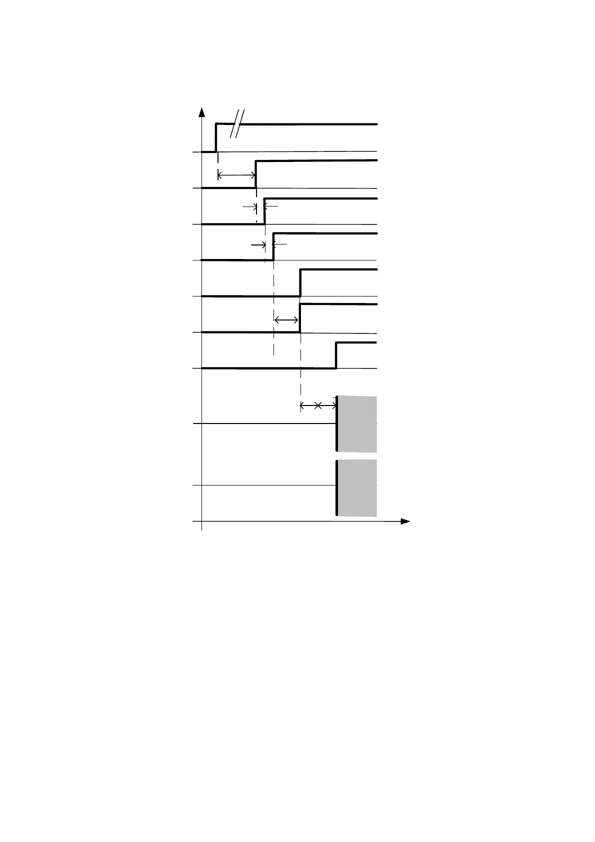
7.7 Timing diagram switch-on sequence
Power On
DOUT3: #ERROR
Controller release
Output stage
switched on
Holding brake
released
Speed Setpoint
Speed actual
value
t1
t2
t3
t4
a / b
Output stage
release
t2
DOUT0: READY
t1 approx. 500 ms Execution of boot program and application start
t2 > 1.6 ms
t3 = 10 ms Depends on the operating mode and the state of the drive
t4a = N x 1.6 ms Can be parameterised (brake parameter run start delay tF)
t4b = approx. 300 ms Time for determination of commutator position
Fig. 7.1 Timing diagram switch-on sequence

 Loading...


