6. Electrical installation
110 Festo.P.BE-CMMS-ST-G2-HW-EN 1008NH
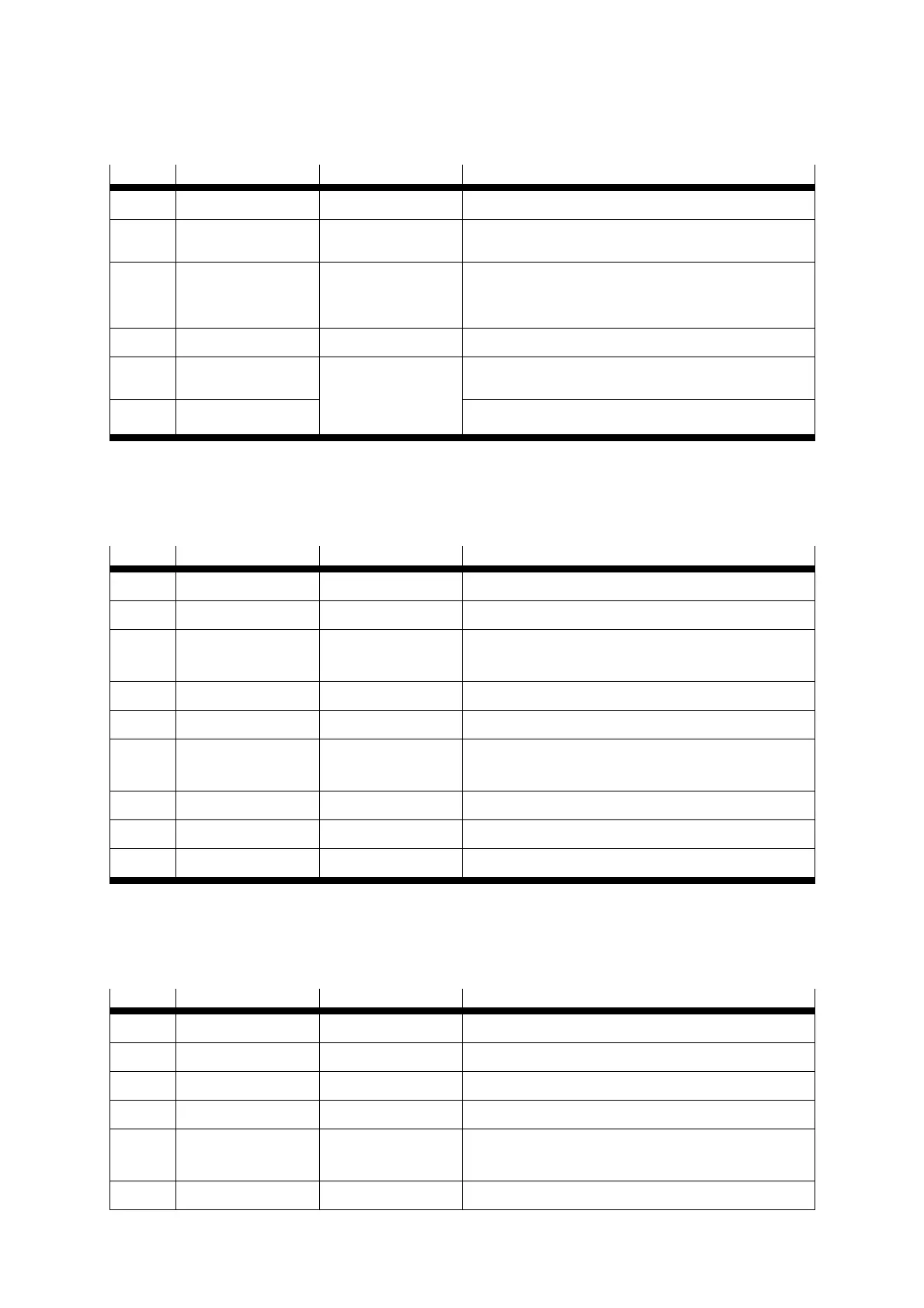
6.4.3 Plug allocation for Safe standstill [X3]
Pin Name Value Specification
1
24 V 24 V DC 24 V DC supply carried out
2
REL 0 V / 24 V DC
Setting and resetting the relay for interrupting the
driver supply
3
0 V
0 V
[GND 24V DC *)]
Reference potential for PLC
[Reference potential for the 24V DC power supply
and for the PLC *)]
4
UNASSIGNED
-
-
5
NC1
Potential-free feedback contact for driver supply,
NC contact
6
NC2
Max. 60V AC
30V DC
2 A
Table 6.7 Pin allocation: Safe standstill [X3]
6.4.4 Field bus CAN [X4]
Pin Name Value Specification
1 -
2 CANL 5 V, Ri = 60 Ohm CAN-low signal line
3 GND - CAN-GND, electrically connected to GND in the
controller
4 - - -
5 Screening - Connection for the cable screen
6 GND - CAN-GND, electrically connected to GND in the
controller
7 CANH 5 V, Ri = 60 Ohm CAN-high signal line
8 - - -
9 - - -
Table 6.8 Pin allocation: Field bus CAN [X4]
6.4.5 RS232/RS-485 [X5]
Pin Name Value Specification
1 -
2 RS232_RxD 10 V, Ri > 2 kOhm Reception line
3 RS232_ TxD 10 V, Ra < 2 kOhm Transmission line
4 RS485_A - -
5 GND 0 V RS232/485 GND, galvanically connected to GND in
the controller
6 - - -

 Loading...


