A. Technical data
Festo.P.BE-CMMS-ST-G2-HW-EN 1008NH 129
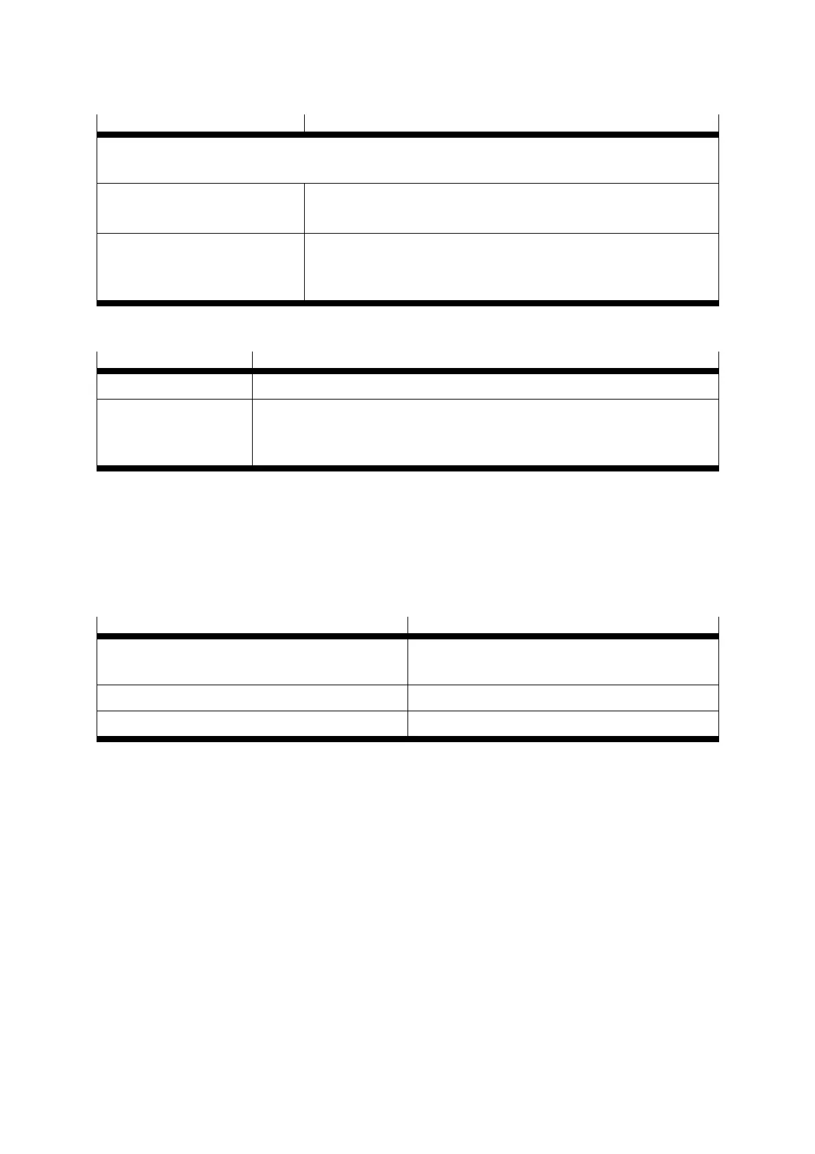
Area Values
Maximum motor cable length for interference emissions as per
EN 61800-3 (conforms to EN 55011, EN 55022)
Second environment
(Industrial)
l ≤ 25 m
Cable capacitance of one phase
against screen or between two
lines
C‘ ≤ 200pF/m
Table A.4 Technical data: Cable data
Sensors Values
Digital sensor N/C contact:
R
cold
< 1 kΩ R
hot
> 10 kΩ
Analogue sensor Silicon temperature probe, e.g. KTY81 … 84
R
25
= 1 kΩ
or R
25
= 2 kΩ
Table A.5 Technical data: Motor temperature monitoring (in preparation)
A.2 Operation and display components
The CMMS-ST stepping motor controller has two LEDs on the front and one seven
segment display for showing the operating status.
Element Function
Seven segment display Displays the operating mode and an error code
should an error occur
Ready LED (green) Ready status
BUS LED (yellow) CAN bus status display
Table A.6 Display components

 Loading...


