4.
5.2.3.2 Mounting CMSH-S-VDE2-… on adapter plate VABA of valve terminal VTOP
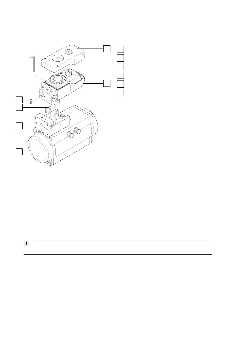
Fig. 13: Mounting CMSH-S-VDE2-… on adapter
plate VABA of valve terminal VTOP
Semi-rotary drive DFPD-...C-VDE2
Adapter plate VABA
Seals
2 M6x20 retaining screws
Housing cover
Positioner CMSH-S-VDE2-…
1.
Make sure that the control plate is mounted on the semi-rotary drive.
2.
Determine the direction of rotation of the semi-rotary drive.
3. Unscrew the 4 housing cover screws and remove the housing cover.
Insert the included seals on the bottom of the pneumatic manifold block into the specified slots.
– Ensure that the seals are correctly positioned.
5.
Insert 2 M6x20 retaining screws into the cut-outs on the pneumatic manifold block.
6. Place the positioner with the shaft adapter on the adapter plate and align it. The swivel angle
must be within the sensing range of the position sensor
è
5.2.1 Mounting the shaft adapter on
the CMSH-S-....
Make sure that transverse loads do not act on the shaft of the positioner during alignment.
7.
Fasten the positioner to the adapter plate with 2 M6x20 retaining screws.
– Tightening torque: 3 Nm ± 10%
8. Place the housing cover on the positioner and tighten the 4 housing cover screws.
–
Make sure that the seal is positioned correctly.
–
Tightening torque: 1 Nm ± 15%