2. Commissioning
2-11
Festo P.BE-CPX-FB32-EN en 1111a
Sequence of addressing Description
1. I/O diagnostic interface
1)
Can be ac tivated by DIL switch. If the interface is ac tivated,
it will occupy the first 16 inputs and outputs in the address
range.
2. Analogue modules Modules with analogue inputs/outputs
3. Technology modules e.g. CP interface, Front End Controller CPX-FEC
4. Digital modules Modules with digital inputs/outputs
1)
Depending on the setting, this address range can also be occupied by status bits
(see note above and Tab. 1/2).
Tab. 2/7: Sequence of addressing
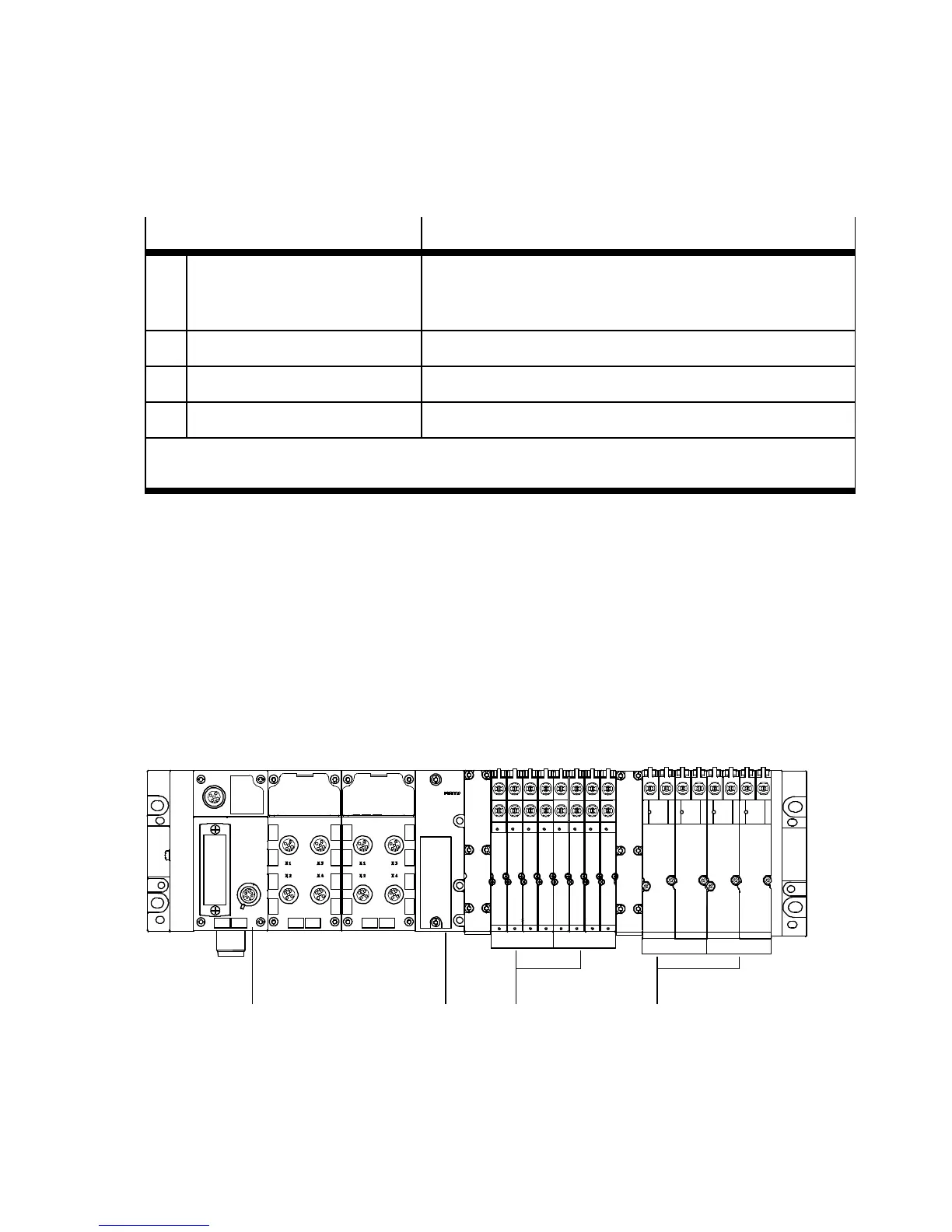
Configuration examples
Example 1: CPX terminal with MPA1- a n d MPA2 pneumatic
The following diagram shows as an example a CPX terminal
with MPA pneumatics and the follo w i ng setting:
– Status bits and I/O diagnostic interface deactivated
Module no.: 0
12
8DI 4DO 8DI
8O
3
8DO
8O
1
23456
4O 4O
4
1
Fieldbus node CPX-FB32
2
MP A pneumatic interface
3
MPA1 pneumatic modules (8 DO each)
4
MPA2 pneumatic modules (4 DO each)
Fig. 2/1: Example terminal 1: (with MPA1- and MPA2 pneumatic)