2. Commissioning
2-12
Festo P.BE-CPX-FB32-EN en 1111a
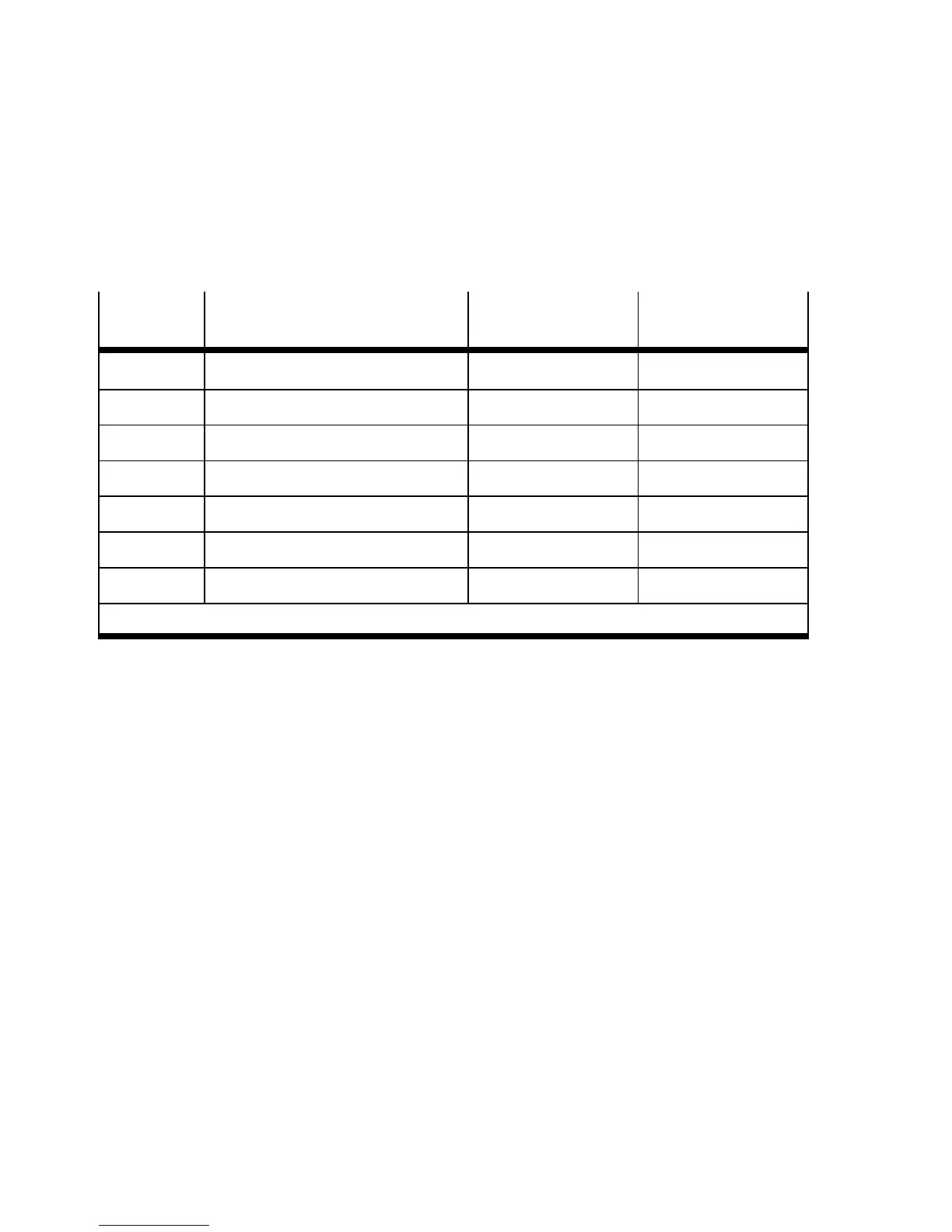
The following table shows the address assignment for the
CPX terminal in Fig. 2/1:
Module
no.
Module Input address Output address
0 Fieldbus node CPX-FB32 – –
1 Digital 8-input module CPX-8DE I0 ... I7 –
2 Digital 4-output module CPX-4DA – O0 ... O7
*)
3 MPA1 pneumatic module (8 DO) – O8 ... O15
4 MPA1 pneumatic module (8 DO) – O16 ... O23
5 MPA2 pneumatic module (4DO) – O24 ... O31
*)
6 MPA2 pneumatic module (4DO) – O32 ... O39
*)
*)
8 bits occupied, 4 bits used
Tab. 2/8: Addressing the example terminal 1 (see Fig. 2/1)
If modular EDS is used, the addresses will be assigned in
bytes. In the example above, the output addresses therefore
change as from modules 2, 5 and 6.
 Loading...