Trouble Shooting
166 © Festo Didactic GmbH & Co. • MPS
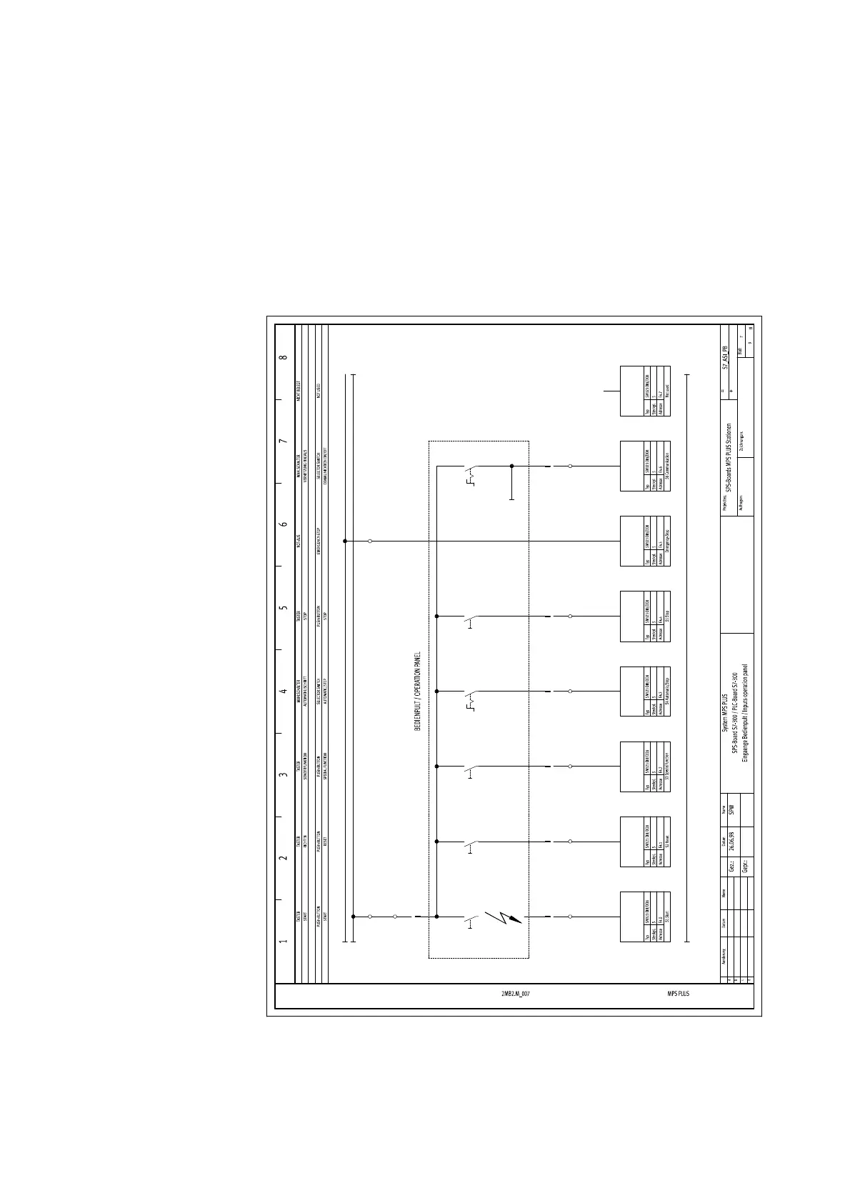
In the following, there is a step-by-step explanation of a sample trouble shooting.
This wiring diagram is not part of the technical documentation of the Distribution
Station, but show a very good example how to measure an error step by step with
different measuring methods.
24NA/6.8
-S5
3
4
-S1
3
4
-S3
3
4
-S2
3
4
-S4
3
4
24V/6.8
-XK1 24V -XK1 24NA
0V/6.8
2
-A2DI1
/6.4
3
-A2DI1
/6.4
4
-A2DI1
/6.4
5
-XMG2
13
-XMG2
14
-XMG2
15
-XMG2
16
-XMG2
17
-XG2 I0 -XG2 I1 -XG2 I2 -XG2 I3 -XG2
-XMG2
21
-XG2 24VB
Disconnection