B. Supplementary summary of components
B−11
Festo P.BE−VTSA−44−EN en 0509NH
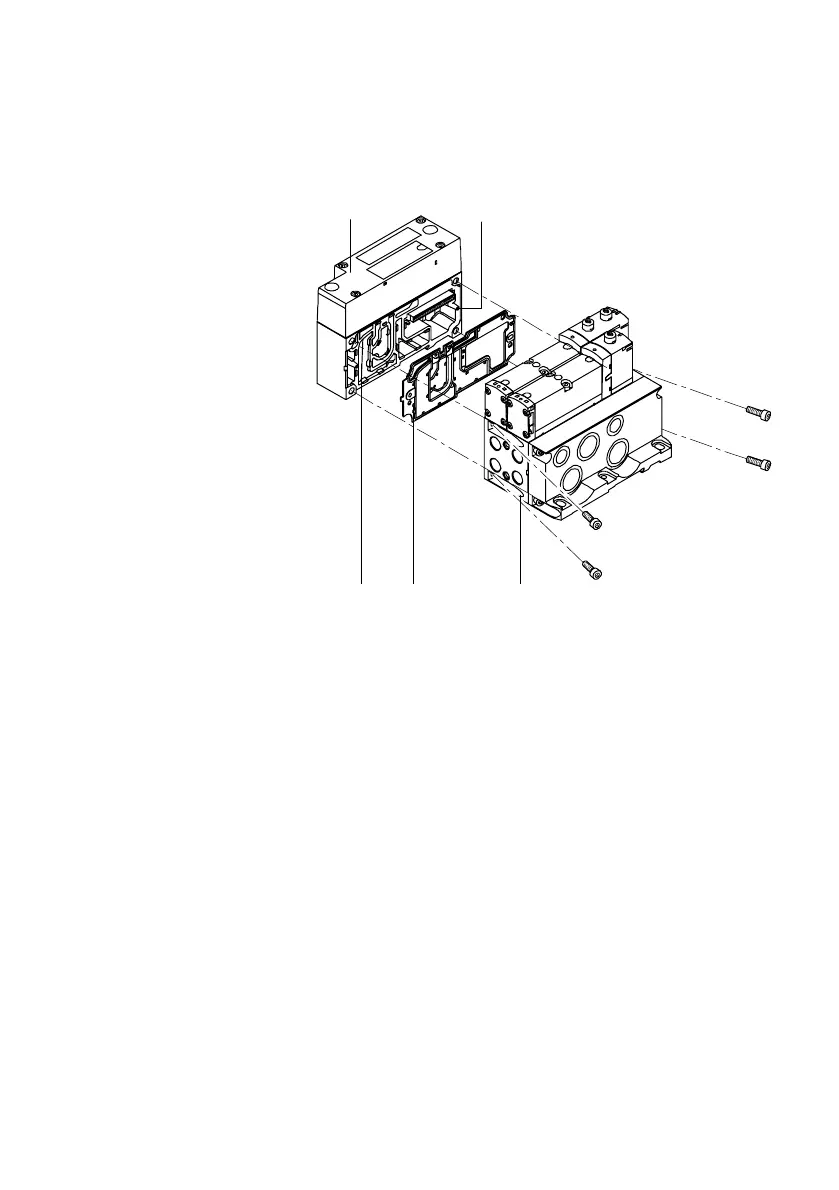
1 Pneumatic
interface
2 Guide pins
3 Pneumatic
manifold block
4 Seal
1 2
34
2
Fig.B/3: Fitting the VTSA valve terminal to the pneumatic interface
3. Push the pneumatic interface together with the pneumatic
manifold blocks, or the pneumatic supply plate. Make
sure that the seal and the components are correctly posi
tioned.