1. Summary of components
1−23
Festo P.BE−VTSA−44−EN en 0509NH
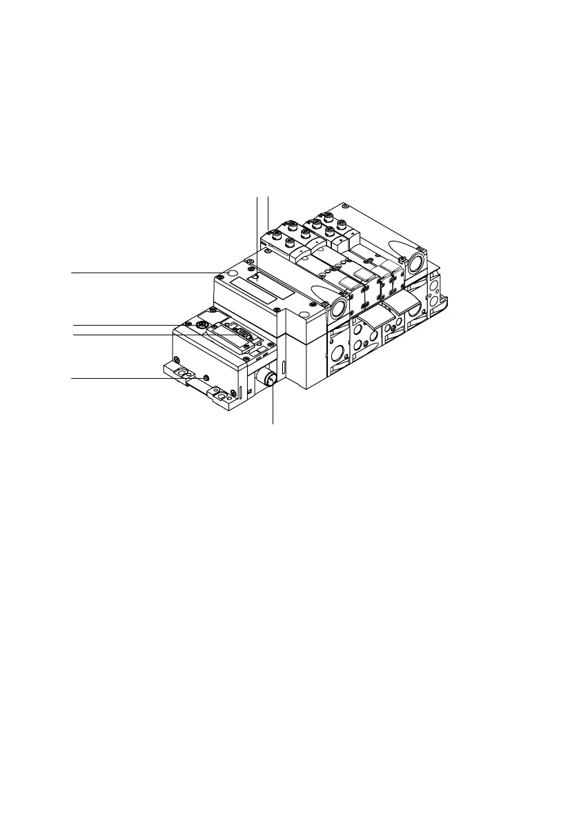
You will find the following electrical connecting and display
elements on the VTSA valve terminal with CPX terminal:
1
2
3
4
5
6
7
1
Inscription field and cover for hat rail
fastening screw
2 Yellow LEDs: signal status display of
the pilot solenoids
3 Voltage supply connection
4 Earth terminal
5 Field bus connection (bus specific)
6 Service interface for handheld, etc.
7 Red LED: common fault display of the
valves
Fig.1/9: Electrical connecting, display and operating elements of the VTSA valve
terminal with CPX terminal