1. Summary of components
1−24
Festo P.BE−VTSA−44−EN en 0509NH
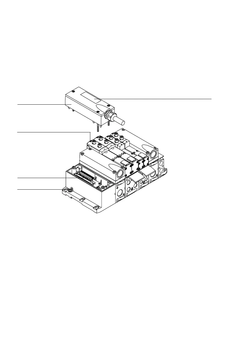
You will find the following electrical connecting and display
elements on the VTSA valve terminal with multipin node
Sub−D:
1
2
3
4
5
1
Sub−D multipin socket with cable
2 Inscription field
3 Earth terminal
4 Sub−D connection
5 Yellow LEDs: signal status display of
the pilot solenoids
Fig.1/10: Electrical connecting and display elements of the VTSA valve terminal with
multipin node Sub−D