1. Summary of components
1−25
Festo P.BE−VTSA−44−EN en 0509NH
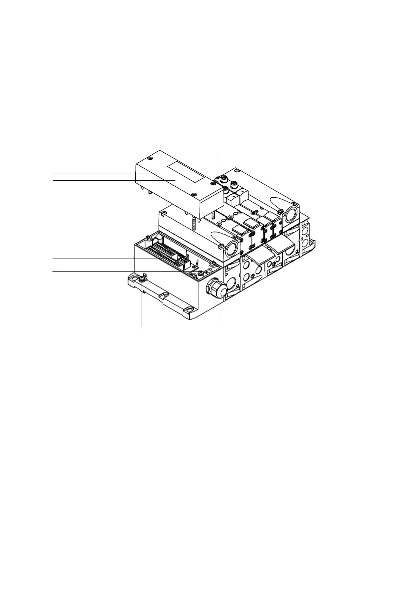
You will find the following electrical connecting and display
elements on the VTSA valve terminal with multipin node
cageclamp:
1
2
3
4
5
6
7
1
Cover
2 Yellow LEDs: signal status display of
the pilot solenoids
3 Cable routing
4 External earth connection
5 Internal earth connection for the
connecting cable
6 Terminal strip
7 Inscription field
Fig.1/11: Electrical connecting and display elements of the VTSA valve terminal with
multipin node cage clamp