COMPONENTS 51
Power supply connectors
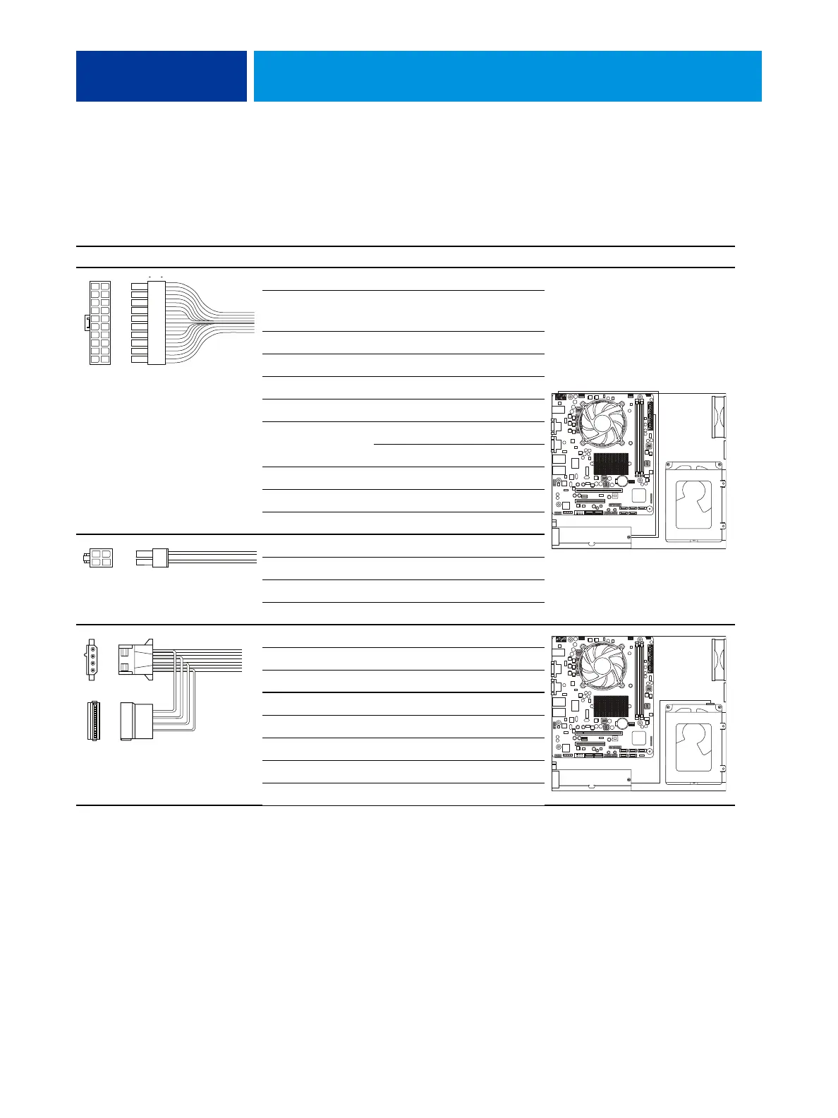
The following table describes the power supply cables that are required in the E100. For more
information about the power supply, see “Specifications” on page 71.
TABLE 2: Power supply cable details
Cable connector Pin(s) Wire color Voltage Connection
NOTE: All voltages listed in this table are direct current voltages (VDC).
1, 2 Orange +3.3V
3, 5, 7, 13, 15,
16, 17
Black COM
4, 6, 19, 20 Red +5V
8GrayPW-OK
9 Purple +5Vsb
10 Yellow +12V
11 Orange +3.3V
Brown +3.3V sense
12 Blue -12V
14 Green PS-ON
18 — not connected
1 Black COM
2 Black COM
3 Yellow&Black +12V
4 Yellow&Black +12V
1 Yellow +12V
2, 3 Black COM
4Red+5V
1 Yellow +12V
2 Black COM
3Red+5V
4 Black COM
5 — not connected
10
9
8
7
6
5
4
3
2
1
20
19
18
17
16
15
14
13
12
11
20-pin power connector
to motherboard
Power supply
to motherboard
2
1
4
3
4-pin power connector
to motherboard
4-pin PATA power (not used)
SATA (5-pin) power connector
to HDD
Power
supply
to HDD