ECS Series Manual — P/N LS10262-001FK-E:A 3/3/2021 47
Installing the FIK-DUAL50W Device Installation
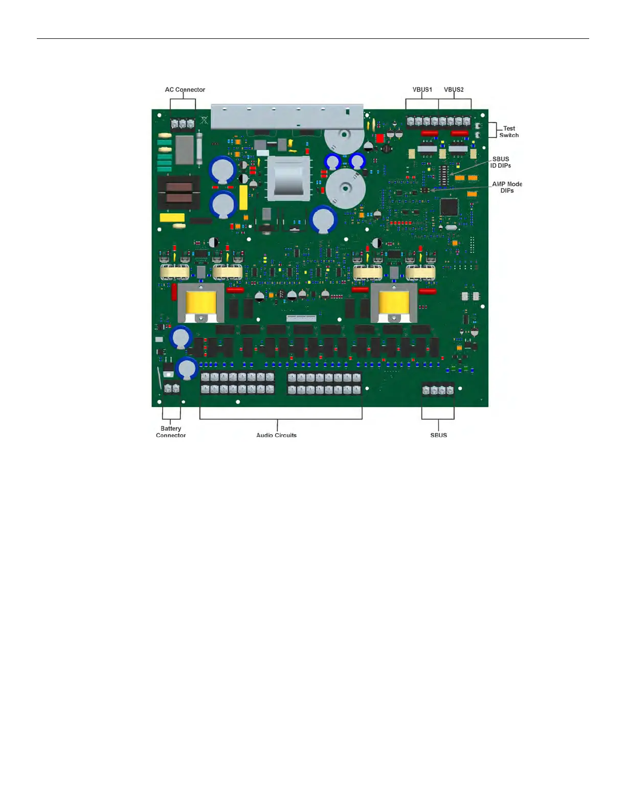
4.7.1 FIK-DUAL50W Board Layout
Figure 4.41 shows the location of terminals, DIP switches and expander connection used in the installation of the FIK-DUAL50W.
Figure 4.41 Components Layout for FIK-DUAL50W
4.7.2 Mounting the FIK-DUAL50W
The FIK-DUAL50W is equipped with a separate enclosure. Refer to Section 3.1 when selecting a mounting location for the FIK-DUAL50W.
The panel should be accessible to main drop wiring runs. It should be mounted as close to the center of the building as possible and located
within a secured area, but should be accessible for testing and service.
Mount the control panel cabinet so it is firmly secured to the wall surface. When mounting on concrete, especially when moisture is
expected, attach a piece of ¾” plywood to the concrete surface and then attach the cabinet to the plywood. Also mount any other modules to
the plywood.
The cabinet can be surface or flush-mounted. If you will be flush-mounting the cabinet, the hole for the enclosure should be 14.5" W x
24.75" H x 3-7/16” D (36.8cm W x 62.9cm H x 8.73cm D). Do not flush-mount in a wall designated as a fire break. The Outside dimensions
of the cabinet are 16.1" W x 26 ½” H x 4-1/8” D (40.64cm W x 66.68cm H x 10.48cm D).