Components of the FT-100/CI and FT-170/CI 2-3
Document 40275-0913
2.2 Components of the FT-100/CI and
FT-170/CI
2.2.1 Introduction
Production information for inspection and rejection is stored and
displayed in the counters menus. Use the information for
detecting production line problems and case rejection issues
quickly and effectively.
The section Using the Reject History Counter
contains more
information.
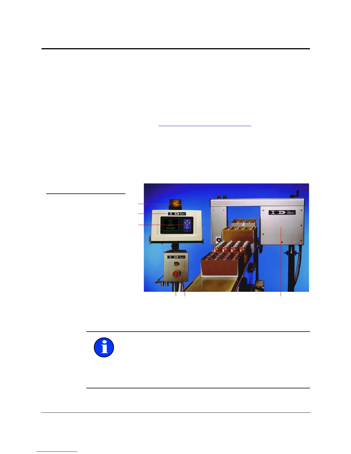
2.2.2 Diagram
Use this diagram to learn about the components that make up the
FT-100/CI and FT-170/CI.
Figure 2-2. Components of the FT-100/CI and FT-170/CI
Note: Failed cases and cases randomly rejected for quality
control purposes are removed from the production line at a
rejection station.
This document does not cover the rejection station operations.
Rejection station operations is described in the Technical
Reference Manual for the FT-100/CI and FT-170/CI products.