3-10 FT-100/CI and FT-170/CI Operation Guide
Document 40275-0913
3.7 Adjusting the Guide Rails
3.7.1 Steps
1. Verify the following conditions.
• Verify that the guide rails are aligned so that they guide
the cases through the inspection head with 3/4-inch
clearance between the side of the case and the
inspection beam plate on the source side.
• Check for skew.
2. Is your FT-100/CI or FT-170/CI equipped with additional flap
inspection sensors?
If yes, check and adjust their positions, if necessary, as
shown below.
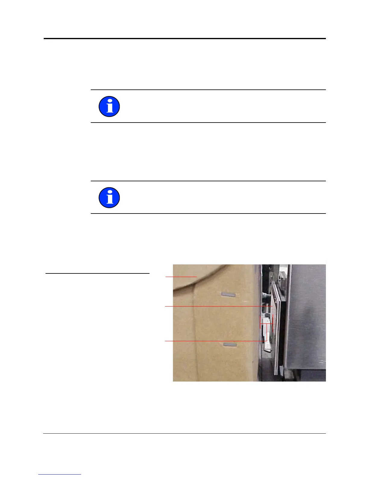
Figure 3-5. Adjusting the Guide Rails
If no, go to the next step.
Note: If any of the conditions are not achieved, contact your
service department for assistance.
Note: The cases must remain perpendicular to the inspection
beam during the inspection process.
1
2
3
No. Description
1 Case being inspected
2 Source side inspection beam plate
3 3/4-inch space between case and
source side inspection beam plate