Operating the FT-100/CI and FT-170/CI 3-13
Document 40275-0913
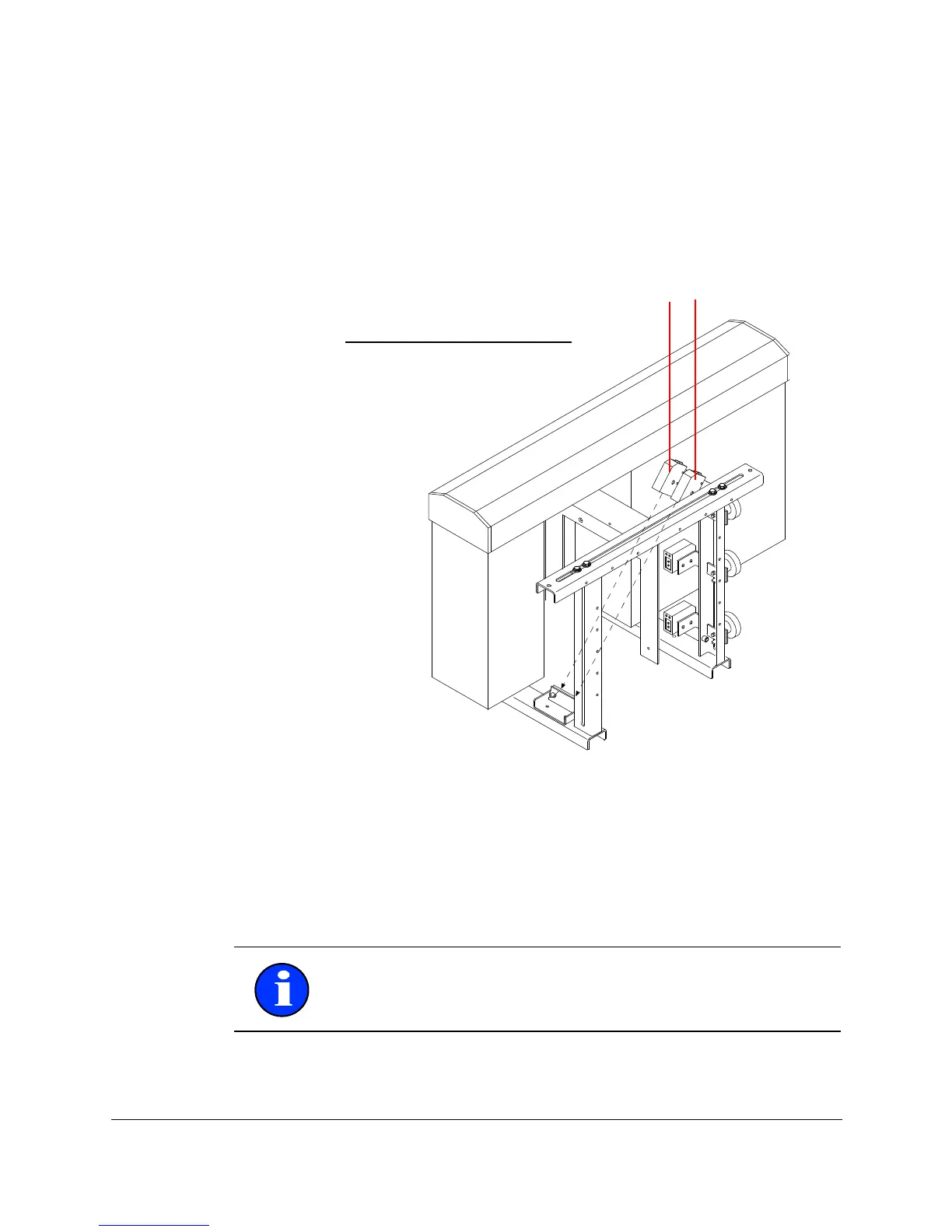
3.8.3 Steps: Adjusting the Leading and Trailing Flap
Sensors
Complete these steps to adjust the leading and trailing flap
sensors.
1. Check and ensure that the each sensor is pointed diagonally
across the front (or rear) of the case so that it is aimed
directly at the reflector.
Figure 3-8. Adjusting the Leading and Trailing Flap Sensor
2. Check the alignment with the leading or trailing flap open
and ensure that the sensor beam intersects the flap approxi-
mately in the middle of the flap edge.
3. Adjust the position of the sensors.
Note: You might also need to adjust the guide rails to position
the case correctly.