–28–
Installing 5800 Series Transmitters
To be sure reception of the transmitter's signal at the proposed mounting
location is adequate, perform a Go/No Go test.
Go/No Go Test Mode
The Go/No Go tests will verify adequate RF signal strength from the proposed
transmitter location, and allow you to reorient or relocate transmitters if
necessary, before mounting the transmitters permanently.
This mode is similar to the transmitter test mode , except that the wireless
receiver gain is reduced. This will enable you to make sure that the RF signal
from each transmitter is received with sufficient signal amplitude when the
system is in the normal operating mode.
1. With at least one 2-line Alpha keypad (FA550KP) connected to the
system, power up the system temporarily. If you had previously
connected the AC transformer to the control panel, you need only plug in
the transformer (to 120VAC outlet) to power up the system.
2. Enter installer code (4112) + [#] + 4 from partition 1's keypad. For multi-
partition systems, make sure all partitions are disarmed before entering
this mode.
3. Once you have placed transmitters in their desired locations and the
approximate length of wire to be run to sensors is connected to the
transmitter's screw terminals (if used), fault each transmitter. Do not
conduct this test with your hand wrapped around the transmitter as this
will cause inaccurate results.
Note:ÊÊOn button type transmitters whose buttons have been set to Arm
Away, Arm Stay, or Disarm, pressing a button will take the system out of
the Go/No Go Test mode and cause that action.
a. The keypad will beep three times to indicate signal reception and
display the appropriate zone number.
b. If the keypad does not beep, reorient or move the transmitter to
another location. Usually a few inches in either direction is all that is
required.
4. If each transmitter produces the proper keypad response when it is
faulted, you can then permanently mount each of the transmitters
according to the instructions provided with them.
5. Exit the Go/No Go test mode by entering: Installer code (4112) + OFF.
6 Unplug the AC transformer.
Setting DIP switches on the 5827 Transmitter(s)
A 5827 transmitter must be set to the programmed House ID, using its DIP
switches.
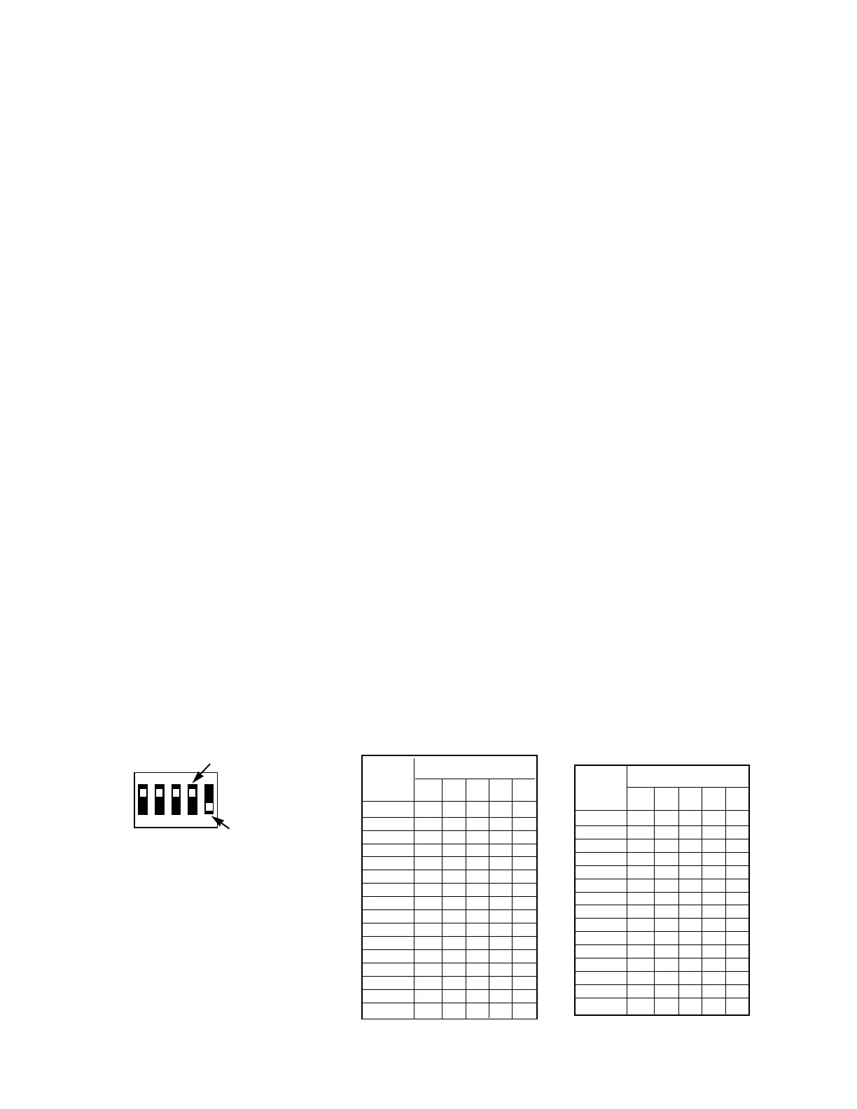
5827 Wireless Keypad DIP Switch Table
1 2 3 4 5
ON
SWITCH UP FOR “ON”
SWITCH DOWN FOR “OFF”
HOUSE ID
SHOWN SET FOR HOUSE ID# 30
HOUSE
DIP SWITCH POSITION
ID
12345
1 ––––UP
2 – – – UP –
3 – – – UP UP
4––UP––
5––UP–UP
6––UPUP–
7––UPUPUP
8 –UP–––
9 – UP – – UP
10 – UP – UP –
11 – UP – UP UP
12 – UP UP – –
13 – UP UP – UP
14 – UP UP UP –
15 – UP UP UP UP
16 UP – – – –
HOUSE
DIP SWITCH POSITION
ID
1 2345
17 UP – – – UP
18 UP – – UP –
19 UP – – UP UP
20 UP – UP – –
21 UP – UP – UP
22 UP – UP UP –
23 UP – UP UP UP
24 UP UP – – –
25 UP UP – – UP
26 UP UP – UP –
27 UP UP – UP UP
28 UP UP UP – –
29 UP UP UP – UP
30 UP UP UP UP –
31 UP UP UP UP UP