–24–
Installation and Setup of the 5881/5882 Receiver
1. Set the receiver's DIP switch for device address Ò0Ó, as described in its
instructions (all switches to the right. . . ÒoffÓ).
=
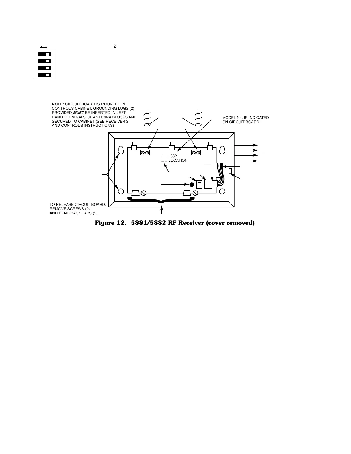
2. Mount the receiver. The RF receiver can detect signals from transmitters
within a nominal range of 200 feet. Take this into consideration when
determining mounting location.
3. Connect the receiver's wire harness to the control's keypad terminals (4,
5, 6, and 7). Plug the connector at the other end of the harness into the
receiver.
4. Refer to the installation instructions provided with the receiver for
further installation procedures regarding antenna mounting, etc.
MOUNTING
HOLES
INTERFERENCE
INDICATOR
LED
CIRCUIT
BOARD
DIP SWITCH
PLUG
&
SOCKET
INSERT IN
RIGHT-HAND
TERMINALS
ANTENNAS
YELLOW
RED
BLACK
GREEN
}
TO CONTROL’S
REMOTE KEYPAD
CONNECTION
POINTS.
WIRING
OPENING
KNOCKOUT
AREA FOR
SURFACE
WIRING
@@@@@@@@e?
@@@@@@@@e?
@@h?
@@h?
@@h?
@@h?
@@h?
@@h?
@@@@@@@@e?@@@@@@@@?e@@@@@@@@e?
@@@@@@@@e?@@@@@@@@?e@@@@@@@@e?
@@@@@@@@
@@@@@@@@
@@
@@
@@
@@
@@
@@
@@
@@
@@
@@
@@
@@
@@
@@
@@
@@
@@
@@
@@
@@
@@
@@
@@
@@
@@
@@
@@
@@
@@
@@
@@
@@
@@
@@
@@
@@
@@
@@
?@@
?@@
?@@
?@@
?@@
?@@
?@@@@@@@@
?@@@@@@@@
?@@@@@@@@?e@@@@@@@@e?@@@@@@@@
?@@@@@@@@?e@@@@@@@@e?@@@@@@@@
@@g
@@g
@@g
@@g
@@g
@@g
@@@@@@@@
@@@@@@@@
@@
@@
@@
@@
@@
@@
@@
@@
@@
@@
@@
@@
@@
@@
@@
@@
@@
@@
@@
@@
@@
@@
@@
@@
@@
@@
@@
@@
@@
@@
@@
@@
5882
LOCATION
}
TO RELEASE CIRCUIT BOARD,
REMOVE SCREWS (2)
AND BEND BACK TABS (2).
MODEL No. IS INDICATED
ON CIRCUIT BOARD
NOTE: CIRCUIT BOARD IS MOUNTED IN
CONTROL’S CABINET, GROUNDING LUGS (2)
PROVIDED
MUST
BE INSERTED IN LEFT-
HAND TERMINALS OF ANTENNA BLOCKS AND
SECURED TO CABINET (SEE RECEIVER’S
AND CONTROL’S INSTRUCTIONS)
Figure 12. 5881/5882 RF Receiver (cover removed)