–31–
Wiring Connections
1. Splice one end of a 3-conductor cable to the wire ends of the 4142TR cable
supplied with the 4300 transformer.
2. Connect the 4142TR cable plug to the 9-pin connector on the control (see
SUMMARY OF CONNECTIONS diagram for location of the 9-pin
connector).
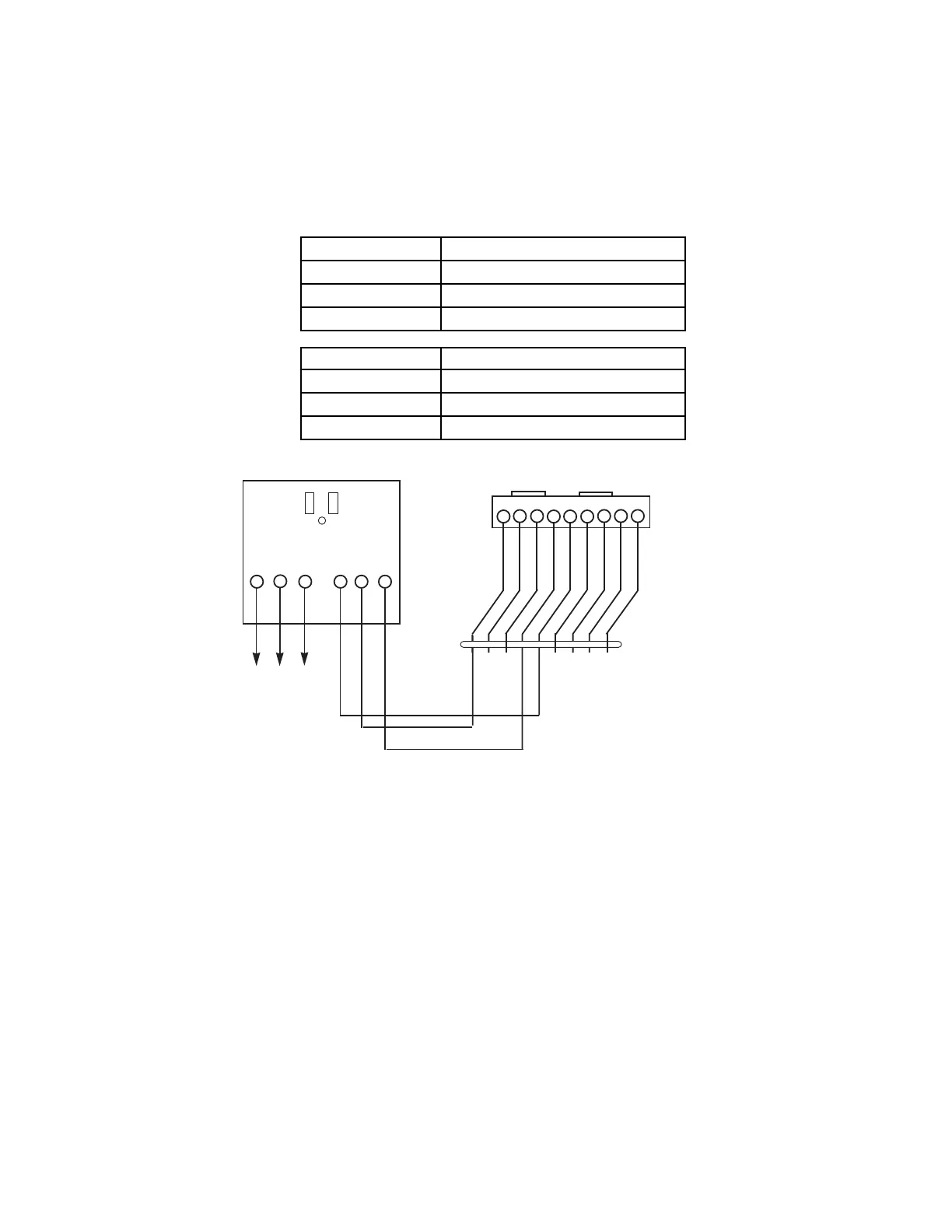
3. Connect the other end of the 3-conductor cable to the 4300 transformer, as
indicated in the table below and in the diagram that follows.
4300 TRANSFORMER WIRE CONNECTIONS
4300 Terminal To Terminal On Control
1Ê(AC) 1ÊÊ(16.5V AC in)
2Ê(Ground) 25ÊEarth Ground terminal
3Ê(AC) 2ÊÊ(16.5V AC in)
4300 Terminal 4142TR Cable Wire
4Ê(Sync) RED (Pin 5 of 9-pin connector)
5Ê(Data) VIOLET (Pin 1 of 9-pin connector)
6Ê(Com) WHITE (Pin 4 of 9-pin connector)
123456789
9-PIN CONNECTOR
ON CONTROL BOARD
BLACK
BLUE
BROWN
GREEN
RED
WHITE
YELLOW
GRAY
VIOLET
4142TR CABLE
1
2
3
4
56
125 2
AC
Earth
Ground
AC
Sync
Data
Com
4300 TRANSFORMER/INTERFACE
TERMINALS
ON CONTROL
BOARD
THESE WIRES (7, 8, 9) NOT USED,
UNLESS 4146 KEYSWITCH
IS ALSO USED
Figure 15. 4300 Transformer Wiring Connections
Programming Relay Outputs
In this system, each device must be programmed as to how to act (ACTION),
when to activate (START), and when to deactivate (STOP). Refer to the
programming procedures for
✱
80 and
✱
81 interactive modes that are provided
in the programming sections of this manual for specific programming details.