–21–
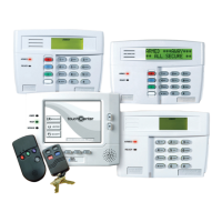
Section 5. WIRED ZONE EXPANSION
This section provides information regarding the use of expansion modules for expanding the
number of wired zones in the system, the modules that can be used and their wiring
connections.
Installing Zone Expansion Units
You can add an additional 8 wired EOLR zones to the basic control's 8 zones,
for a total of 16 wired zones, by using a No. 4219 Wired Expansion Unit, or
4229 Wired Expansion/Relay Unit.
Location ¥ You can mount an expansion unit within the control
cabinet if space permits. Otherwise, mount the unit
outside the cabinet.
Supervision ¥ Units are supervised against removal. Keypads will
display CHECK and zone 09 if a zone expander is
disconnected.
¥ Units have tamper protection for security when
mounted outside of the cabinet.
Zone Information ¥ Assign zone numbers 10Ð17 for the eight wired
expansion loops (designated A to H). You can
program these zones individually (in
✱
56 interactive
mode) for Partition 1 or 2. Expansion zones must
also be programmed as input type 2 (AW) when
prompted.
Connections and Set-Up
1. Connect the 4219 or 4229 module to the control's keypad terminals (see
diagram below).
1 2 3 4 5
OFF ON
ON
@@@@@@@@e?
@@@@@@@@e?
@@h?
@@h?
@@h?
@@h?
@@h?
@@h?
@@@@@@@@e?@@@@@@@@?e@@@@@@@@e?@@@@@@@@?e@@@@@@@@e?@@@@@@@@?e@@@@@@@@e?@@@@@@@@?e
@@@@@@@@e?@@@@@@@@?e@@@@@@@@e?@@@@@@@@?e@@@@@@@@e?@@@@@@@@?e@@@@@@@@e?@@@@@@@@?e
@@@@@@@@
@@@@@@@@
@@
@@
@@
@@
@@
@@
@@
@@
@@
@@
@@
@@
@@
@@
@@
@@
@@
@@
@@
@@
@@
@@
@@
@@
@@
@@
@@
@@
@@
@@
@@
@@
@@
@@
@@
@@
@@
@@
@@
@@
@@
@@
@@
@@
@@
@@
@@
@@
@@
@@
@@
@@
@@
@@
@@
@@
@@
@@
@@
@@
@@
@@
@@
@@
@@
@@
@@
@@
@@
@@
@@
@@
@@
@@
@@
@@
@@
@@
@@
@@
@@
@@
@@
@@
@@
@@
?@@
?@@
?@@
?@@
?@@
?@@
?@@@@@@@@
?@@@@@@@@
?@@@@@@@@?e@@@@@@@@e?@@@@@@@@?e@@@@@@@@e?@@@@@@@@?e@@@@@@@@e?@@@@@@@@?e@@@@@@@@
?@@@@@@@@?e@@@@@@@@e?@@@@@@@@?e@@@@@@@@e?@@@@@@@@?e@@@@@@@@e?@@@@@@@@?e@@@@@@@@
@@g
@@g
@@g
@@g
@@g
@@g
@@@@@@@@
@@@@@@@@
@@
@@
@@
@@
@@
@@
@@
@@
@@
@@
@@
@@
@@
@@
@@
@@
@@
@@
@@
@@
@@
@@
@@
@@
@@
@@
@@
@@
@@
@@
@@
@@
@@
@@
@@
@@
@@
@@
@@
@@
@@
@@
@@
@@
@@
@@
@@
@@
@@
@@
@@
@@
@@
@@
@@
@@
@@
@@
@@
@@
@@
@@
@@
@@
@@
@@
@@
@@
@@
@@
@@
@@
@@
@@
@@
@@
@@
@@
@@
@@
=
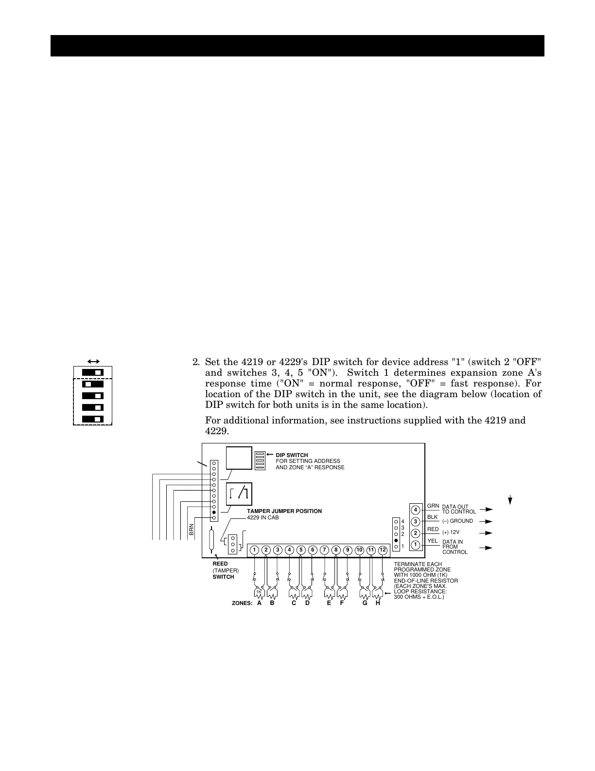
2. Set the 4219 or 4229's DIP switch for device address "1" (switch 2 "OFF"
and switches 3, 4, 5 "ON"). Switch 1 determines expansion zone A's
response time ("ON" = normal response, "OFF" = fast response). For
location of the DIP switch in the unit, see the diagram below (location of
DIP switch for both units is in the same location).
For additional information, see instructions supplied with the 4219 and
4229.
BRN
12345678
9 101112
1
2
3
4
GRN
DATA OUT
TO CONTROL
BLK
(–) GROUND
RED
(+) 12V
YEL
DATA IN
FROM
CONTROL
4
3
2
1
TERMINATE EACH
PROGRAMMED ZONE
WITH 1000 OHM (1K)
END-OF-LINE RESISTOR
(EACH ZONE'S MAX.
LOOP RESISTANCE:
300 OHMS + E.O.L.)
➞
ZONES: A B C D E F G H
1K
DIP SWITCH
FOR SETTING ADDRESS
AND ZONE “A” RESPONSE
➞
REED
(TAMPER)
SWITCH
➞
TAMPER JUMPER POSITION
4229 IN CABINET
(NOT TAMPERED)
4229 REMOTE
(TAMPER PROTECTED)
TB1
4229
TB2
4-PIN CONSOLE PLUG
➞
EITHER OR BOTH CAN BE USED
➞
➞
WHT
GRY
VIO
BLK
YEL
ORG
NO
NC
C
GND
NO
NC
C
RLY
2
RLY
1
RELAYS
"OFF"
RELAY
CONNECTOR
NO C NC
▲
▲
{
{
{
➞
RELAY
2
}
}
RELAY
1
TERMINALS ON
CONTROL PANEL
(TERM 6)
(TERM 4)
(TERM 5)
(TERM 7)
Figure 11. Wiring Connections, 4219 & 4229 (4229 shown)