–42–
Making the Battery Connections
1. Use the battery standby formula (above) to select the appropriate battery
for the installation.
Do not connect the battery until all devices have been wired to the control.
2. Attach the Red and Black wires on the battery connector cable as follows:
a) Red to the positive (+) battery tab on the control board.
b) Black to the negative (Ð) battery tab on the control board.
See the SUMMARY OF CONNECTIONS diagram for location of the (+)
and (Ð) battery tabs on the control board.
3. Attach the Red and Black wires at the other end of the battery connector
cable as follows:
a) Red to the positive (+) terminal on the battery.
b) Black to the negative (Ð) terminal on the battery.
Battery Tests: The battery is periodically tested automatically
(approximately every four hours), and if it cannot sustain a
load, a low battery message is displayed and, if so
programmed, will be reported to the central station.
In addition, the connection to the battery is checked every
3 minutes (CSFM requirement). If there is no battery
detected, or a low battery condition detected, a low battery
message is displayed and a report is sent to the central
station.
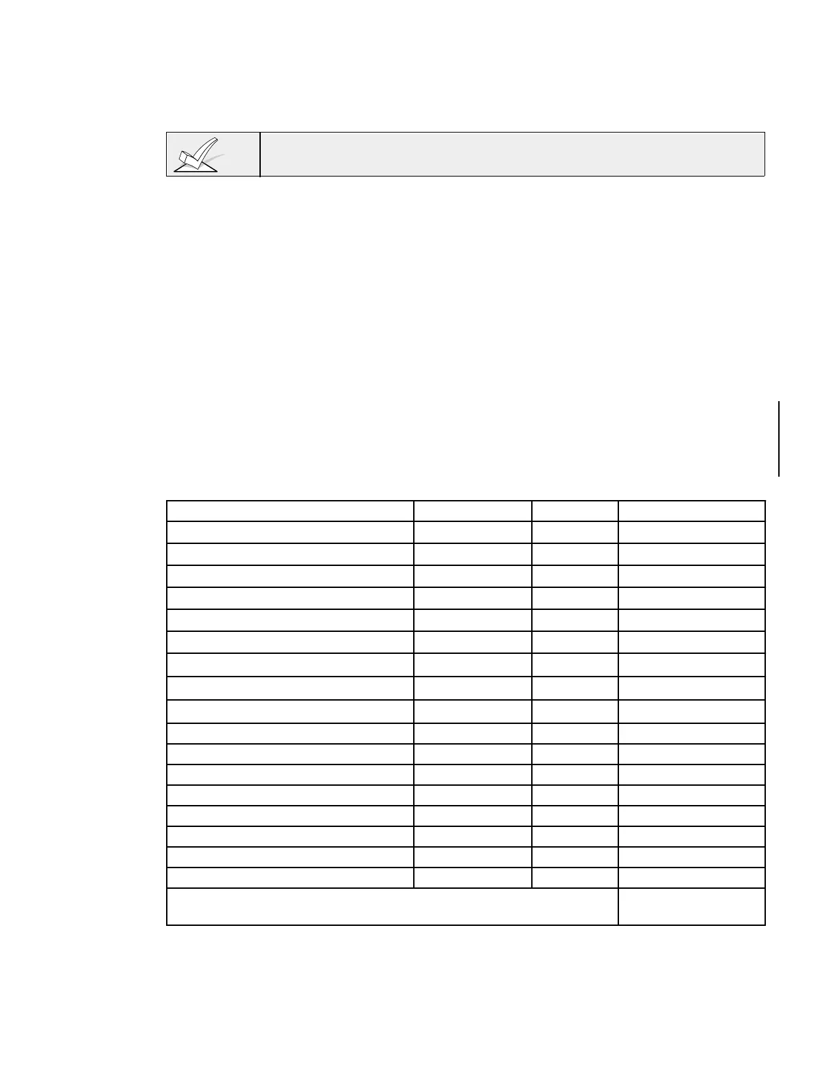
AUXILIARY DEVICE CURRENT DRAW WORKSHEET
DEVICE CURRENT # UNITS TOTAL CURRENT
FA210KP Keypad 30 mA
FA250KP Keypad 120 mA
FA450KP Keypad 140 mA
FA550KP & FA550KPR (red) Keypad 140 mA
5881/5882 RF Receiver 35mA
4219 Zone Expander 35mA
4204 Relay Unit 15/180mA
à
4229 Zone Expander/Relay Unit 35/100mA
à
FA4285 Phone Module 160mA
*
*
*
*
TOTAL =
ÊÊÊÊÊÊÊÊÊÊÊÊÊÊÊÊÊÊÊÊÊÊÊÊÊÊÊ(Current available from Aux. terminals = 600 mA max.)**
ÊÊ* ÊIf using hard-wire devices such as PIRs, refer to the specifications for that particular unit's current
draw.
**Ê In UL installations, maximum current draw from the Auxiliary Output and the Alarm Output
combined must not exceed 700 mA (600 mA max from Auxiliary Output).
Êà
Ê
Figures are for relays OFF/relays ON.