Instruction Manual
D103412X012
Detailed Setup—OS Function Block
July 2013
167
drop the good downstream block out of Cas mode for one evaluation cycle and then restore Cas mode. This initializes
the upstream controller to the remaining good region of control.
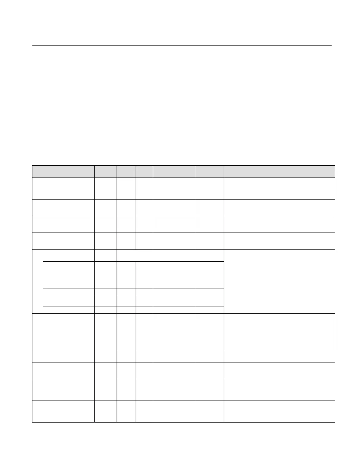
OS Function Block Parameter List (table 4‐48)
Read/Write Capability: RO - Read Only, RW - Read Write
Mode: The block mode(s) required to write to the parameter
Double indentation and shaded Index Number indicates sub‐parameter
Table 4‐48. Output Splitter Function Block Parameter Definitions
Label
PARAMETER_NAME
Index
Number
RO /
RW
Block
Mode
Range
Initial
Value
Description
Static Revision
ST_REV
1 RO N/A 0 to 65535 0
Data Type: Unsigned16
The revision level of the static data associated with the
function block. The revision value will be incremented each
time a static parameter value in the block is changed.
Tag Description
TAG_DESC
2 RW ALL 7 bit ASCII Spaces
Data Type: Octet String
The user description of the intended application of the
block.
Strategy
STRATEGY
3 RW ALL 0 to 65535 0
Data Type: Unsigned 16:
The strategy field can be used to identify grouping of
blocks. This data is not checked or processed by the block.
Alert Key
ALERT_KEY
4 RW ALL 1 to 255 0
Data Type: Unsigned8
The identification number of the plant unit. This information
may be used in the host for sorting alarms, etc.
Block Mode
MODE_BLK
5
Data Type: DS‐69
The actual, target, permitted, and normal modes of the
block.
Target: The requested block mode
Actual: The current mode of the block
Permitted: Allowed modes for Target
Normal: Most common mode for Target
TARGET
5.1 RW
7:OOS
3:AUTO
2:CAS
OOS until
block
configured,
then last
valid target
ACTUAL
5.2 RO OOS
PERMITTED
5.3 RW OOS+AUTO+CAS
OOS AUTO
CAS
NORMAL
5.4 RW AUTO+CAS
Block Error
BLOCK_ERR
6 RO N/A
1: Block
Configuration Error
7: Input Failure/Bad
PV Status
8: Output Failure
14: Power‐up
15: Out‐of‐Service
Dynamic
Data Type: Bit String
0
=Inactive
1
=Active
This parameter reflects the error status associated with the
hardware or software components associated with a block.
It is a bit string, so that multiple errors may be shown.
Setpoint
SP
7 PV_SCALE +/- 10%
Data Type: DS‐65
Analog setpoint of the block
Output 1
OUT_1
8
MAN
OOS
OUT_SCALE
+/- 10%
Data Type: DS‐65
The primary analog output value calculated as a result of
executing the function (the first output value and status).
Output 2
OUT_2
9
MAN
OOS
OUT_SCALE
+/- 10%
Data Type: DS‐65
The primary analog output value calculated as a result of
executing the function (the second output value and
status).
Output 1 Range
OUT_1_RANGE
10 RO
EU at 100%
EU at 0 %
Unit Index
Decimal Point
100
0
%
2
Data Type: DS‐68
The high and low scale values, engineering units code, and
number of decimal places to be used in displaying the OUT
value, this parameter has no effect on this block.
-Continued-
 Loading...


