Instruction Manual
D103412X012
Detailed Setup—AI Function Block
July 2013
177
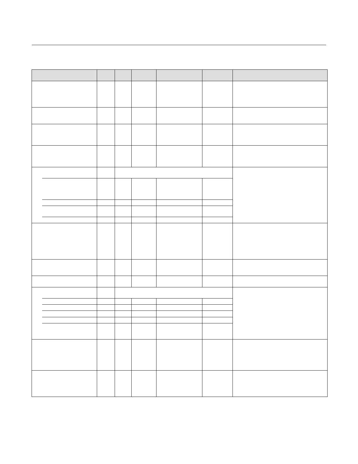
Table 4‐57. Analog Input Block Parameter Definitions
Label
PARAMETER_NAME
Index
Number
RO /
RW
Write Block
Mode
Range
Initial
Value
Description
Static Revision
ST_REV
1 RO N/A 0 to 65535 0
Data Type: Unsigned16
The revision level of the static data associated with
the function block. The revision value will be
incremented each time a static parameter value in
the block is changed
Tag Description
TAG_DESC
2 ALL 7 bit ASCII spaces
Data Type: Octet String
The user description of the intended application of
the block.
Strategy
STRATEGY
3 ALL 0 to 65535 0
Data Type: Unsigned16
The strategy field can be used to identify grouping
of blocks. This data is not checked or processed by
the block.
Alert Key
ALERT_KEY
4 ALL 1 to 255 0
Data Type: Unsigned8
The identification number of the plant unit. This
information may be used in the host for sorting
alarms, etc.
Block Mode
MODE_BLK
5
Data Type: DS‐69
Valid Bits: 7: OOS, 4: MAN, 3: AUTO
The actual, target, permitted, and normal modes of
the block.
Target: The requested block mode
Actual: The current mode of the block
Permitted: Allowed modes for Target
Normal: Most common mode for Target
TARGET 5.1 RW ALL
OOS
MAN
AUTO
OOS until block
is configured,
then last valid
target
ACTUAL 5.2 RO ALL OOS
PERMITTED 5.3 RW ALL OOS+MAN+AUTO
OOS, MAN,
AUTO
NORMAL 5.4 RW ALL AUTO
Block Error
BLOCK_ERR
6 RO
1: Block Configuration
Error
3: Simulate Active
7: Input Failure/ Bad PV
Status
14: Power‐up
15: Out‐of‐Service
Data Type: Bit String
0
=Inactive
1
=Active
Error status associated with the hardware or
software for the AI block.
Process Value
PV
7 RO
PV Status set equal to
FIELDV_VAL Status
Data Type: DS‐65
Reflects the scaled value from the configured
channel. Units set by OUT_SCALE and L_TYPE.
Primary Output
OUT
8 OOS, MAN OUT_STATE
Data Type: DS‐68
The block output value and status.
Simulate
SIMULATE
9
Data Type: DS‐82
A group of data that contains the current transducer
value and status, the simulated transducer value
and status, and the enable/disable bit.
SIMULATE_STATUS 9.1 ALL 0
SIMULATE_VALUE 9.2 ALL 0
TRANSDUCER_STATUS 9.3 RO 0
TRANSDUCER_VALUE 9.4 RO 0
ENABLE/DISABLE 9.5 ALL
0=Not Initialized
1=Simulation Disabled
2=Simulation Active
1=simulate
disabled
Transducer Scale
XD_SCALE
10 OOS
EU at 100%
EU at 10%
Units Index
Decimal Point
100
0
%
2
Data Type: DS‐68
Transducer scaling (XD_SCALE) is applied to the
value from the channel to produce the FIELD_VAL in
percent. The XD_SCALE units code must match the
channel units code (if one exists), or the block will
remain in OOS mode after being configured.
Output Scale
OUT_SCALE
11 OOS
EU at 100%
EU at 10%
Units Index
Decimal Point
100
0
%
2
Data Type: DS‐68
The high and low scale values, engineering units
code, and number of decimal places to be used in
displaying the OUT parameter and parameters
which have the same scaling as OUT.
-Continued-
 Loading...


