Instruction Manual
D103412X012
Detailed Setup—AI Function Block
July 2013
178
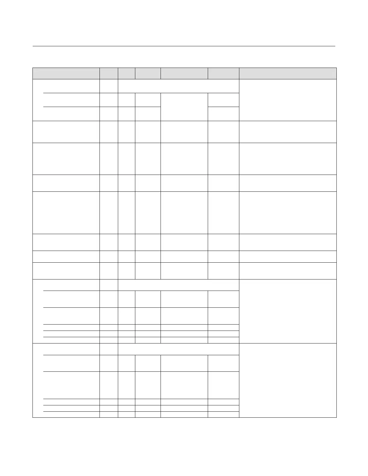
Table 4‐57. Analog Input Block Parameter Definitions (Continued)
Description
Initial
Value
Range
Write Block
Mode
RO /
RW
Index
Number
Label
PARAMETER_NAME
Grant Deny
GRANT_DENY
12
Data Type: DS‐70
Options for controlling access of host computer and
local control panels to operating, tuning, and alarm
parameters of the block.
GRANT: 0=N/A, 1=granted
DENY: 0=N/A, 1=denied
GRANT 12.1 ALL
Valid Bits
0: Program
1: Tune
2: Alarm
3: Local
All bits: 0
DENY 12.2 ALL All bits: 0
I/O Options
IO_OPTS
13 OOS 10: Low cutoff All bits: 0
Data Type: Bit String
0=Disable
1=Enable
User options for Output Control.
Status Options
STATUS_OPTS
14 OOS
3: Propagate Failure
forward
6: Uncertain if Limited
7: Bad if Limited
8: Uncertain in Man
Mode
All bits: 0
Data Type: Bit String
0=Disable
1=Enable
User options for Status
AI Channel
CHANNEL
15 OOS See table 4‐54 0: Undefined
Data Type: Unsigned16
Used to select the type of threshold that is used to
set the output.
Linearization Type
L_TYPE
16 OOS, MAN
0: Undefined
1: Direct
2: Indirect
3: Ind. Sqr. Root
0: Undefined
Data Type: Enum
Linearization type. Determines whether the field
value is used directly (Direct), is converted linearly
(Indirect), or is converted with the square root
(Indirect Square Root). The OUT_SCALE is normally
the same as the transducer, but if L_TYPE is set to
Indirect or Ind Sqr Root, OUT_SCALE determines the
conversion from FIELD_VAL to the output.
Low Cutoff
LOW_CUT
17 ALL Positive 0
Data Type: Float
If calculated output is below this value the output is
0.
Process Value Filter Time
PV_FTIME
18 ALL Positive 0
Data Type: Float
Time constant of first order filter on PV, in seconds.
Field Value
FIELD_VAL
19 RO 0
Data Type: DS‐65
Value of the field device analog input, with a status
reflecting the Transducer condition.
Updated Event
UPDATE_EVT
20
Data Type: DS‐73
This alarm is generated whenever a static parameter
is changed.
UNACKNOWLEDGED 20.1 RW N/A
0=Undefined
1
=Acknowledged
2
=Unacknowledged
0=Undefined
UPDATE_STATE 20.2 RO N/A
0=Undefined
1
=Update reported
2
=Update not reported
0=Undefined
TIME_STAMP 20.3 RO N/A 0
STATIC_REVISION 20.4 RO N/A 0
RELATIVE_INDEX 20.5 RO N/A 0
Block Alarm
BLOCK_ALM
21
Data Type: DS‐72
The block alarm is used for all configuration,
hardware, connection failure or system problems in
the block. The cause of the alert is entered in the
subcode field.
UNACKNOWLEDGED 21.1 RW
0=Undefined
1
=Acknowledged
2
=Unacknowledged
ALARM_STATE 21.2 RO
0=Undefined
1
=Clear‐reported
2
=Clear‐not reported
3
=Active‐reported
4
=Active‐not reported
TIME_STAMP 21.3 RO
SUBCODE 21.4 RO
VALUE 21.5 RO
-Continued-
 Loading...


