Instruction Manual
D103412X012
Detailed Setup—DO Function Block
July 2013
196
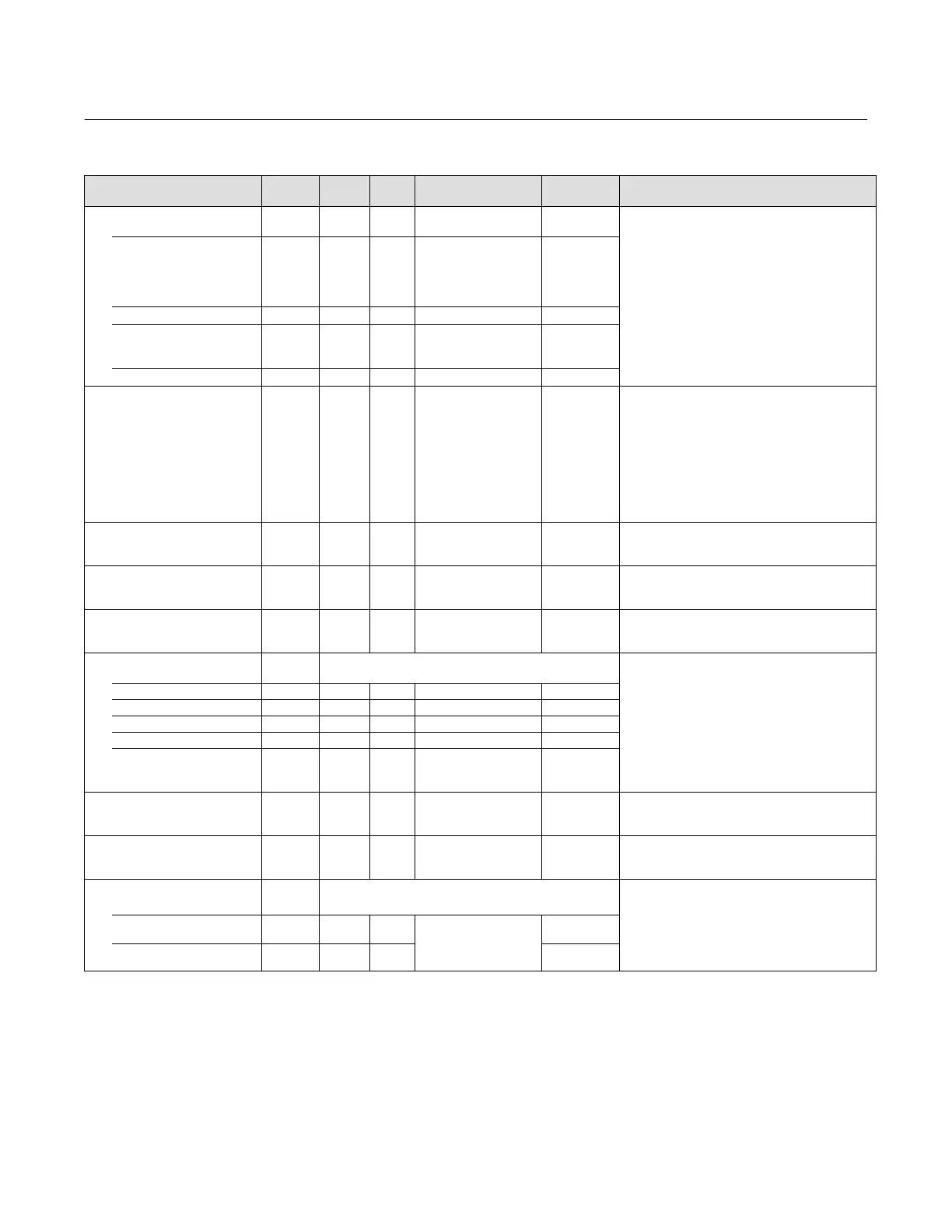
Table 4‐72. Discrete Output Function Block Parameter Definitions (Continued)
DescriptionInitial ValueRangeMode
RO /
RW
Index
Number
Label
PARAMETER_NAME
Block Mode
MODE_BLK
5
Data Type: DS‐69
Valid Bits: 7: OOS, 5: LO, 4: MAN, 3: AUTO
2: CAS, 1: RCAS
The actual, target, permitted, and normal modes of
the block.
Target: The requested block mode
Actual: The current mode of the block
Permitted: Allowed modes for Target
Normal: Most common mode for Target
TARGET
5.1 RW ALL
OOS
MAN
AUTO
AUTO‐CAS, AUTO‐RCAS
OOS until
block is
configured,
then last valid
target
ACTUAL
5.2 RO ALL OOS
PERMITTED
5.3 RW ALL
OOS+MAN+AUTO+
CAS+RCAS
OOS+MAN+A
UTO+CAS
+RCAS
NORMAL
5.4 RW ALL AUTO+CAS
Block Error
BLOCK_ERR
6 RO N/A
1: Block Configuration
Error
3: Simulate Active
4: Local Override
5: Device Fault State Set
7: Input Failure / Bad PV
Status
8: Output Failure
14: Power‐up
15: Out‐of‐Service
Dynamic
Data Type: Bit String
0=Inactive
1=Active
This parameter reflects the error status associated
with the hardware or software components
associated with a block. It is a bit string, so that
multiple errors may be shown.
Process Value Discrete
PV_D
7 RO N/A
PV_D Status set equal
to Readback_D Status
Dynamic
Data Type: DS‐66
The discrete process variable calculated from
READBACK_D.
Setpoint Discrete
SP_D
8
OOS
MAN
AUTO
PV_STATE
Data Type: DS‐66
The discrete target block output value (set point).
Output Discrete
OUT_D
9 MAN OUT_STATE
Data Type: DS‐66
Position target of valve. 0=closed, 1=open, 2-100
position the value in 5% steps.
Simulate Discrete
SIMULATE_D
10
Data Type: DS‐83
Allows the transducer discrete input or output to
the block to be manually supplied when simulate is
enabled. When simulation is disabled, the simulate
value and status track the actual value and status.
SIMULATE_STATUS 10.1 ALL 0
SIMULATE_VALUE 10.2 ALL 0
TRANSDUCER_STATUS 10.3 RO 0
TRANSDUCER_VALUE 10.4 RO 0
ENABLE/DISABLE 10.5 ALL
0=Not initialized
1=Simulation Disabled
2=Simulation Active
1
Process Value State
PV_STATE
11 ALL 0
Data Type: Uint16
Index to the text describing the states of a discrete
output.
Transducer State
XD_STATE
12 ALL 0
Data Type: Uint16
Index to the text describing the states of a discrete
for the value obtained from the transducer.
Grant Deny
GRANT_DENY
13
Data Type: DS‐70
Options for controlling access of host computers
and local control panels to operating, tuning, and
alarm parameters of the block.
GRANT:0=N/A, 1=granted
DENY: 0=N/A, 1=denied
GRANT 13.1 N/A
0: Program
1: Tune
2: Alarm
3: Local
All bits: 0
DENY 13.2 N/A All bits: 0
-Continued-
 Loading...


