Instruction Manual
D103412X012
Maintenance and Troubleshooting
July 2013
244
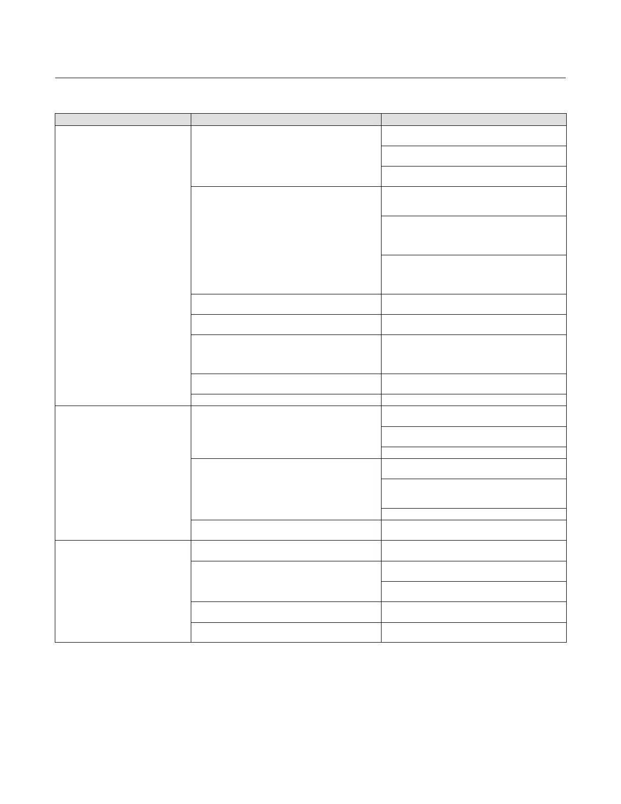
Table 7‐2. Instrument Troubleshooting
Symptom Possible Cause Action
1 Instrument will not communicate. 1a No power to device
1a1 Ensure device is connected to the segment (see
host system documentation).
1a2 Measure the terminal voltage. Terminal voltage
should be between 9 and 32 VDC.
1a3 Check to be sure device is drawing current. There
should be approximately 19 mA.
1b Internal device wiring problems.
1b1 Verify connectors are plugged into the printed
wiring board correctly (see Printed Wiring Board
Assembly on page 239).
1b2 Check continuity of cable between terminal box
and printed wiring board. If necessary, replace the
terminal box assembly (see Replacing the Terminal Box
on page 242).
1b3 Check for damaged printed wiring board lands and
terminals. If necessary, replace the terminal box
assembly (see Replacing the Terminal Box on page
242).
1c Incompatible network settings 1c Change host parameters. Refer to host
documentation for procedure.
1d Defective printed wiring board (PWB) assembly. 1d Replace printed wiring board (see Replacing the
PWB Assembly on page 239.
1e Defective terminal box. 1e Check continuity from each screw terminal to the
corresponding PWB connector pin. If necessary, replace
the terminal box assembly (see Replacing the Terminal
Box on page 242).
1f Defective Field Communicator or ValveLink
modem cable.
1f If necessary, repair or replace cable.
1g Fieldbus card defective or not compatible with PC. 1g Replace Fieldbus card.
2 Device does not stay on segment. 2a Incorrect signal level.
2a1 Check that segment is properly terminated (see
host system documentation).
2a2 Wrong cable type or segment length too long. See
Site Planning Guide.
2a3 Bad power supply or conditioner.
2b Excess noise on segment.
2b1 Check integrity of wiring connections. Make sure
cable shield is grounded only at the control system.
2b2 Check for corrosion or moisture on terminals in
terminal box (refer to page 242 for terminal box
information).
2b3 Check for bad power supply.
2c Electronics failing. 2c. Replace printed wiring board assembly (see
Replacing the PWB Assembly on page 239).
3 A value cannot be written to a
parameter.
3a Resource block parameter Write Lock may be set to
Locked.
3a Change Write Lock to Not Locked (refer to page 45).
3b If a transducer block parameter, the mode may be
incorrect or the parameter may be protected.
3b1 Check table 4‐14. If necessary change the
transducer block target mode to Manual.
3b2 Check table 4‐14. If necessary change data
protection.
3c You have attempted to write a value that is outside
the valid range.
3c Check the range values listed for the parameter
(refer to the parameter tables in Section 4).
3.d Function block or in/out block mode may be
incorrect.
3.d. Confirm that block is in correct mode for writing to
any given parameter.
-Continued-
 Loading...


