Instruction Manual
D103412X012
Maintenance and Troubleshooting
July 2013
247
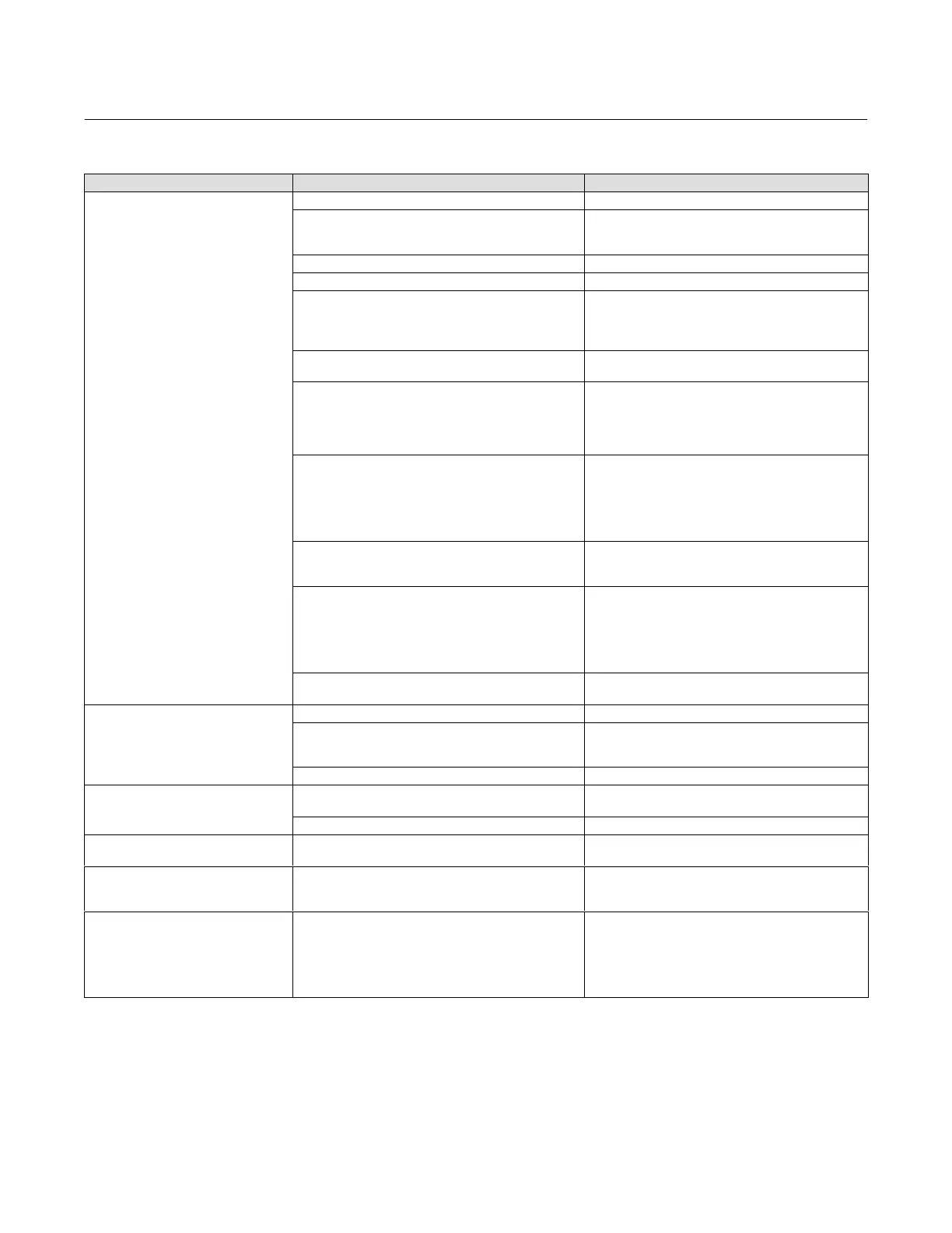
Table 7‐2. Instrument Troubleshooting (Continued)
ActionPossible CauseSymptom
14 Instrument will not calibrate, has
sluggish performance or oscillates.
14a Travel sensor failed. 14a Replace the housing (key 1)
14b Travel feedback is out of accepted range 14b Check the mounting. Ensure the correcting
mounting kit has been selected and the magnetic array
is properly installed.
14c Cables not plugged into PWB correctly. 14c Inspect connections and correct.
14d Configuration errors. 14d Verify configuration. Use Device Setup on page 40.
14e Restricted pneumatic passages in I/P converter 14e Check screen in I/P converter supply port of the
module base. Replace if necessary. If passages in I/P
converter restricted, replace I/P converter (see
Replacing the I/P Converter on page 238).
14f O‐ring(s) between I/P converter ass'y missing or hard
and flattened losing seal.
14f Replace O‐ring(s) (refer to the I/P Converter section
on page 237).
14g I/P converter ass'y damaged/corroded/clogged. 14g Check for bent flapper, open coil (continuity),
contamination, staining, or dirty air supply. Coil
resistance should be between 1680 ‐ 1860 ohms.
Replace I/P ass'y if damaged, corroded, clogged, or
open coil (see Replacing the I/P Converter on page 238).
14h I/P converter ass'y out of spec. 14h I/P converter ass'y nozzle may have been adjusted.
Verify drive signal (55 to 80% for double‐acting; 60 to
85% for single‐acting) with the valve off the stops.
Replace I/P converter ass'y if drive signal is continuously
high or low (see Replacing the I/P Converter on page
238).
14i Defective module base seal. 14i Check module base seal for condition and position.
If necessary, replace seal. Refer to Module Base
Maintenance on page 234.
14j Defective relay. 14j Depress relay beam at adjustment location in
shroud, look for increase in output pressure. Remove
relay, inspect relay seal. Replace relay seal or relay if I/P
converter ass'y good and air passages not blocked
(refer to Replacing the Pneumatic Relay on page 240).
Check relay adjustment (refer to page 215).
14k Defective 67CFR regulator, supply pressure gauge
jumps around.
14k Replace 67CFR regulator.
15 Instrument will not calibrate.
15a Configuration errors. 15a Verify configuration.
15b Magnet assembly is not correctly installed. 15b Check the mounting. Ensure the correcting
mounting kit has been selected and the magnetic array
is properly installed.
15c Cables not plugged into PWB correctly. 15c Inspect connections and correct.
16 ValveLink diagnostic tests provide
erroneous results.
16a Defective pressure sensor(s). 16a Replace PWB (see Replacing the PWB Assembly on
page 239).
16b Pressure sensor O‐ring(s) missing. 16b Replace O‐ring(s).
17 Cannot perform advanced
diagnostics.
17a Instrument does not have proper tiering. 17a Upgrade tiering.
18 A PlantWeb alert is active, but not
reported (broadcast) automatically.
18a PlantWeb alerts in firmware 1.5 and higher are
mode‐based. Transducer block mode may be in MAN or
OOS.
18a Check transducer block mode. Change to AUTO if
appropriate.
19 Field Communicator does not turn
on.
19a Battery pack not charged. 19a Charge battery pack.
Note: Battery pack can be charged while attached to the
Field communicator or separately. The Field
Communicator is fully operable while the battery pack is
charging. Do not attempt to charge the battery pack in
a hazardous area.
 Loading...


