Instruction Manual
D103412X012
Installation
July 2013
23
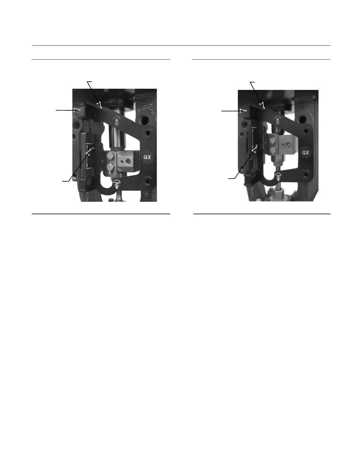
Figure 2‐15. Air‐to‐Open Fisher GX Magnet Assembly
Alignment
W9218
ALIGNMENT TEMPLATE
INDEX MARK
RETAINING
SLOT
Figure 2‐16. Air‐to‐Close Fisher GX Magnet Assembly
Alignment
W9219
INDEX MARK
ALIGNMENT TEMPLATE
RETAINING
SLOT
5. Tighten the fasteners and remove the alignment template. Continue on with the appropriate step 6 below.
Air‐to‐Open GX Actuators
6. The pneumatic output port on the DVC6215 lines up with the integral GX actuator pneumatic port. See figure 2‐17.
7. Using a 5 mm hex wrench, attach the feedback unit to the GX actuator mounting pad on the side that has the open
pneumatic port. Be sure to place the O‐ring between the feedback units pneumatic output and the actuator
mounting pad. Pneumatic tubing between the feedback unit and the actuator is not required because the air
passages are internal to the actuator.
8. Connect the pneumatic tubing from the DVC6205f to the feedback units pneumatic port provided on the front of
the DVC6215 as shown in figure 2‐17.
9. Check for clearance between the magnet assembly and the DVC6215 feedback slot.
10. If not already installed, install a vent in the port on the upper diaphragm casing's air supply connection on the
actuator yoke leg.
 Loading...


