Instruction Manual
D103412X012
Installation
July 2013
35
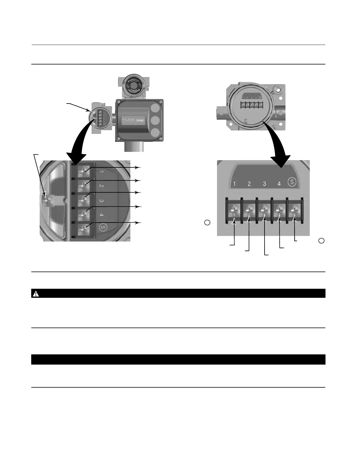
Figure 2‐26. Terminal Details for Connecting the Base Unit and Feedback Unit for Remote‐Mounted Digital Valve
Controllers
FEEDBACK CONNECTIONS
TERMINAL BOX
FEEDBACK UNIT
TO FEEDBACK UNIT TERMINAL 1
TO FEEDBACK UNIT TERMINAL 2
TO FEEDBACK UNIT TERMINAL 3
GROUND
SCREW
TERMINAL 1
TERMINAL 3
TERMINAL 2
X0131-FF
BASE UNIT
FEEDBACK UNIT
FEEDBACK
CONNECTIONS
TERMINAL BOX
TO FEEDBACK UNIT TERMINAL 4
TERMINAL 4
TO FEEDBACK UNIT TERMINAL S
USING CABLE SHIELD
TERMINAL S
WARNING
The cable shield is typically not insulated. It is required that you insulate the cable shield prior to installation.
When connecting the cable shield in step 8 ensure that the uninsulated shield wiring does not contact the DVC6215
housing. Failure to do so can result in ground loop issues.
8. Connect the cable shield between terminal S on the feedback unit and terminal S on the base unit.
CAUTION
Failure to secure the cable wires in the support clips in step 9 can cause wires to break in applications with high levels of
vibration.
9. Secure the cable wires, using the support clips in the DVC6215 feedback unit (as shown in figure 2‐27), to help
prevent shifting and movement of the wires.
10. Replace and hand‐tighten all covers.
 Loading...


