Instruction Manual
D103412X012
Detailed Setup—Transducer Block
July 2013
85
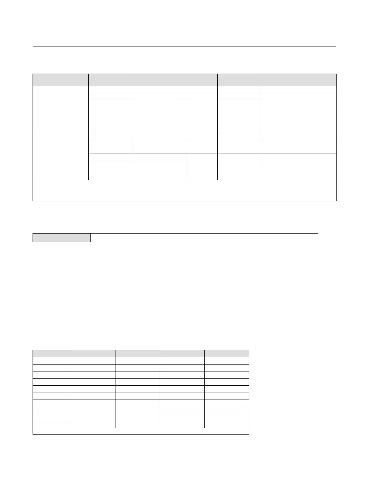
Table 4‐11. Output Block PV Status
FEATURE_SEL
PW Alarms Set PV Status
Transducer Mode,
Actual
Active PlantWeb
Alarms
AO / DO
PV Status
(2)
AO / DO
PV Substatus
AO/DO PV
Limit Substatus
(1)
Enabled
OOS X Bad Device Failure Constant
Man X Bad Non‐specific Constant
Auto Fail Uncertain Subnormal See table 4‐12
Auto Maintenance, no Fail Uncertain Non‐specific See table 4‐12
Auto
Advisory, no Fail, no
Maintenance
Good Advisory See table 4‐12
Auto None Good Non‐Specific See table 4‐12
Not Enabled
OOS X Bad Device Failure Constant
Man X Bad Non‐Specific Constant
Auto Fail Good Non‐Specific See table 4‐12
Auto Maintenance, no Fail Good Non‐Specific See table 4‐12
Auto
Advisory, no Fail, no
Maintenance
Good Non‐Specific See table 4‐12
Auto None Good Non‐Specific See table 4‐12
NOTES:
X
= No Effect
1. PV limit substatus reflects only READBACK limit substatus. SP limit substatus reflects only out block rate limits.
2. Firmware Revision 1.1 and earlier will set AO/DO PV Status to Bad if Feedback Sensor has failed, i.e.; Travel Sensor Fail. However, if the Travel Sensor fails, and the instrument falls back to
pressure, PV Status will remain good.
MAI Channel Map
Field Communicator TB > Configure/Setup > Detailed Setup > MAI Channel Map
Allows the user to specify which transducer block parameter is available through each of the MAI Block channels
(MAI_CHANNEL_1 through MAI_CHANNEL_8 [95.1 through 95.8]). Transducer block parameters available to each
channel:
11 = FINAL_VALUE
12 = TRAVEL_TARGET
13 = FINAL_POSITION_VALUE
14 = TRAVEL
15 = SUPPLY_PRESS
16 = ACT_PRESS_A
17 = ACT_PRESS_B
18 = ACT_PRESS_DIFF
19 = DRIVE_SIGNAL
10 = TRAVEL_DEVIATION
11 = TEMPERATURE
12 = CYCLE_COUNT
13 = TRAVEL_ACCUM
Table 4‐12. Limit Sub Status
Out Block Transducer Mode In Cutoff Region Rate Limited Limit Sub‐Status
AO, DO OOS X X Constant
AO, DO MAN X X Constant
AO AUTO High X High Limited
AO AUTO Low X Low Limited
AO AUTO X High High Limited
AO AUTO X Low Low Limited
AO AUTO None None Not Limited
DO AUTO X High High Limited
DO AUTO X Low Low Limited
DO AUTO X None Not Limited
NOTE: X = No Effect
 Loading...


