Medium Connections Multi-DENCO
68 FläktGroup DC-2013-0101-GB • Subject to modifications • R5-08/2020
If the heat rejection unit(s) are installed ABOVE the Multi-DENCO unit, for the dis-
charge line:
– The height separation must be no larger than the maximum values shown on Fig. 6-
4 & Fig. 6-5.
– 'P' traps must be installed at the bottom of EVERY vertical riser in the discharge line,
including pipework outside of riser cupboards (Detail 1)
– For every max. 5 m of vertical pipework an 'S' trap must be installed (Detail 2)
– At the top of every riser a bend should be used to prevent oil return (Detail 3)
– Use a 1% slope in the direction of refrigerant flow (Detail 3 & 4)
When the condenser is located BELOW the Multi-DENCO unit:
– Oil traps are not required for vertical droppers
– However, oil traps are required for ANY vertical risers
– Consideration must be given to ensure that the liquid line pressure losses are not
excessive (see chapter 6.2.3 "Sizing" for more information).
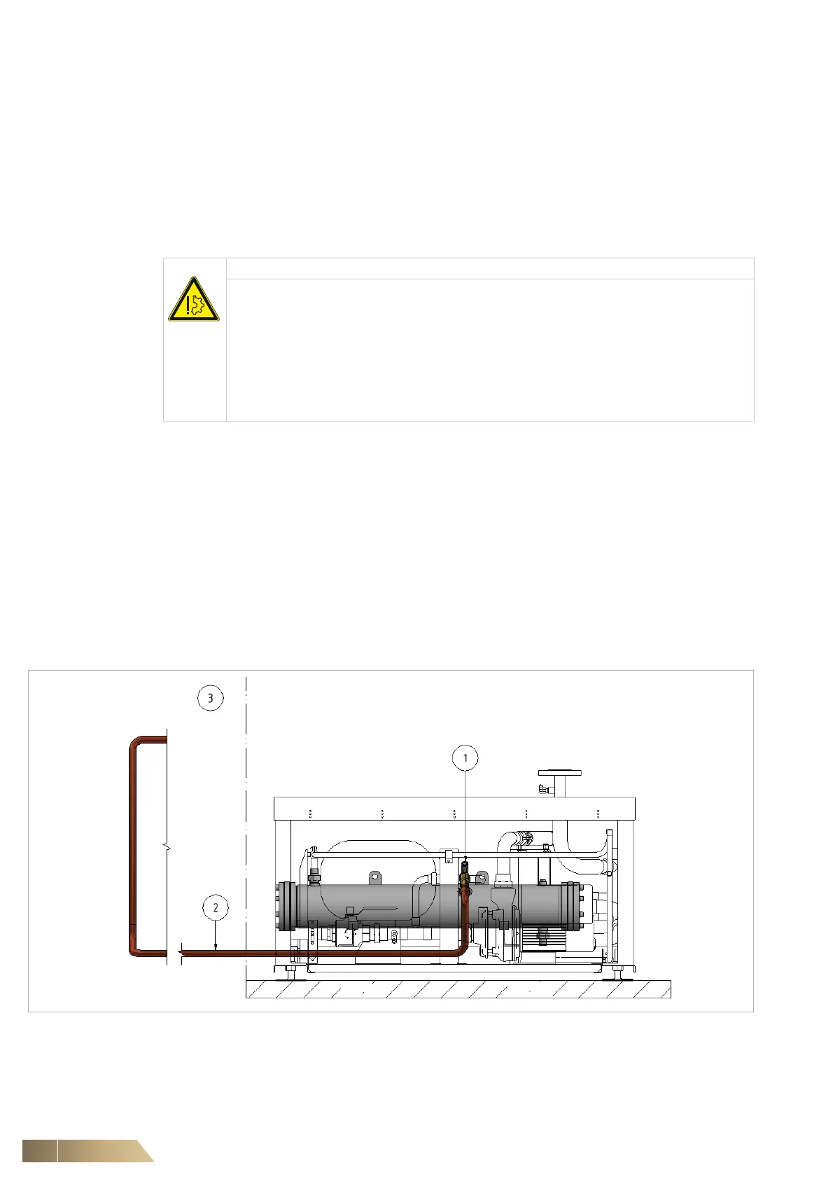
6.2.10 Installing an exhaust line for the pressure relief valve
Any system that includes a pressure relief valve (PRV) (1 in Fig. 6-6 and Fig. 6-7) will
require an exhaust line (2 in Fig. 6-6) must be installed to direct any refrigerant dis-
charged to the outside environment (3 in Fig. 6-6). The exhaust pipework can exit the
watercool module in any direction and the installation must adhere to EN 378-2.
Fig. 6-6
NOTICE
Failure to install sufficient oil traps can cause a lack of lubrication in a compressor
resulting in poor performance or failure.
The last trap (detail 3 in Fig. 6-4) prevents liquid migration back towards the com-
pressor.
If liquid migrates to the compressor it will saturate the oil and can cause a 'flooded
start'. This can then lead to 'liquid slugging' where liquid refrigerant enters the
compressor's scroll, causing irreversible damage.
• Ensure suitable oil traps are installed as per Fig. 6-4.