Manual LogoMatic G2
14
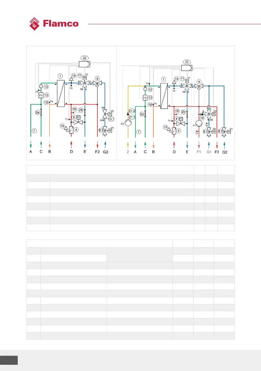
Hydraulic diagram
LogoMatic G2 UC
LogoMatic G2 MC-UC-DHWC
(e.g. with optional DWC)
Legend: Connections ¾" MT (without optional ball valves)
UC MC MC-UC
A Cold water outlet for dwelling, (second CW connection) A A A
B Domestic hot water outlet for dwelling (HW) B B B
C Cold water inlet building connection (CW) C C C
D Heating flow line building connection (FL heating) D D D
E Heating return line building connection (RL heating) E E E
F1/F2 Heating flow line for dwelling heating circuit (FL dwelling), F1-MC / F2-UC F2 F1 F1/F2
G1/G2 Heating return line for dwelling heating circuit (RL dwelling), G1-MC / G2-UC G2 G1 G1/G2
Z Domestic water circulation Z (depending on variant) - Z Z
Overview of sensors/actors designations
Temperature sensors (2-wire) UC MC MC-UC
T1 Flow line Primary side T1 T1 T1
T2 Return line T2 T2 T2
T3 Return line MC T3 T3
T4 Domestic hot water Secondary side PHE outlet T4 T4 T4
T5 CW (and DWC if available) Secondary side PHE inlet T5 T5 T5
T7 Flow line MC T7 T7
Valves and pumps (3-/ 4-wire)
V1 Return line, primary side DWH/heating V1 V1 V1
V2 Heating circuit return line (and mixing valve in case of MC) V2 V2 V2
V3 Zone valve UC Servomotor, optional V3 V3
V4 Zone valve MC Servomotor, optional V4 V4
P1 Heating circuit pump MC P1 P1
P2 DWC pump with optional DWC P2 P2
Primary UC
Primary UCMC