Manual LogoMatic G2
22
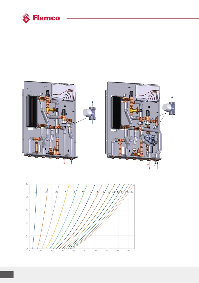
4.3 Zone valve for heating circuit
Setting:
• Remove the protective cap (white).
• Valve presetting ring with slotted screwdriver: close the valve by doing 2 turns and then set the
desired number (1-9). The number 11 means one turn open and then set to 1.
• Take the setting for the desired heating system flow rate from the design documents and adjust
it accordingly.
Variants depicted: UC / MC-UC
Reference value diagram(setting curves) for setting the zone valve (Kvs = 1.8):
Please notice the separately enclosed installation instructions when for the living space control
which is optionally available.
FL RL
UC
FL RL
UC
MC
Volume flow[l/h]
Pressure reduction through the zone valve [bar]