Manual LogoMatic G2
20
4. Individual station components (depending on variant)
4.1 Optional heat meter installation
The heat meter may only be installed once the entire heating system has been flushed through.
LogoMatic G2 stations are fitted with an adaptor (L = 110 mm, 2 x 3/4") for a heat meter which must
be removed before the heat meter is installed.
The corresponding instructions for the HFM must be followed.
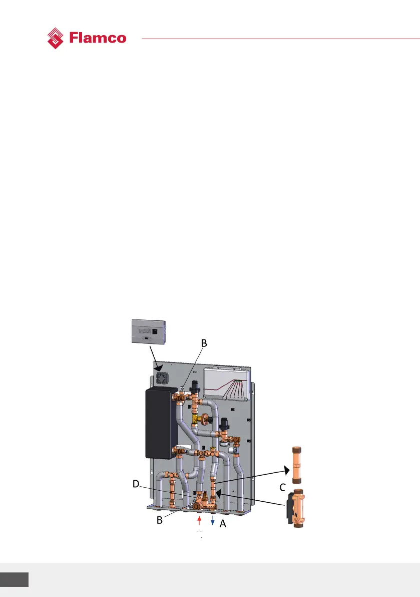
Procedure:
1. Close all shut-o valves "A" in the station (if present).
2. Lower the system pressure by opening bleeding device "B". WARNING: Water may leak from
thesystem.
3. Release the screw fittings on adaptor "C". WARNING: Water may leak from the system. (The
station can be drained using bleeding device "B" below or the BFD ball valves, where installed.)
4. Remove the adaptor and insert the heat meter and screw in place. NOTE: Observe the direction
of flow, use seals.
5. Remove the M10x1 plug at "D" and screw in and seal the heat meter supply sensor.
6. Once the work is complete, re-open the shut-o valves and use the bleeding devices to bleed
the station. Perform a leak-tightness check.
FL RL
prim.